
Industrial Controller
All product are in stock,guaranteed delivery within 3-7 days.


PRODUCT
PICTURE
BRAND
DESCRIBE
STOCK
DOWNLOAD
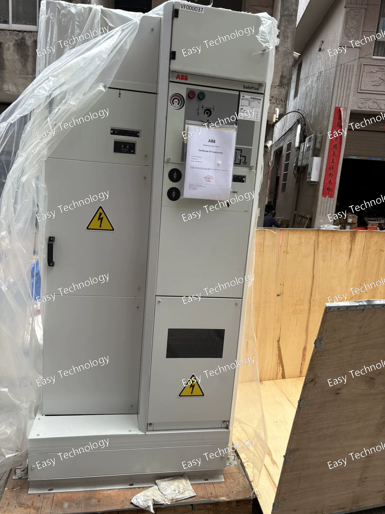
Technical Specifications / Parameters Parameter Specification Manufacturer Part Number VF000037 Product Type Non-Metallic (Plastic) Enclosure / Wireway / Junction Box Material High-Impact, Fiberglass-Reinforced Polyester (FRP) or equivalent robust thermoplastic. Provides excellent corrosion resistance. Color Gray (Standard ABB industrial gray) Protection Rating NEMA 4X / IP66 • Dust-tight (No ingress of dust) • Protected against powerful water jets from any direction. • X indicates corrosion resistance. Dimensions (Approx.) Refer to official drawing for exact size. Typical for a 6x8x4 inch or similar medium-sized trough. (Example only: ~150mm x 200mm x 100mm [H x W x D]) This must be verified. Mounting Multiple mounting options: typically includes mounting feet or flange with pre-molded holes for wall, panel, or DIN rail mounting inside. Cover Transparent or opaque hinged cover with a robust latch and integral gasket for secure, watertight sealing. Sealing Continuous, compressible silicone or EPDM gasket between base and cover. Drilling / Entry Pre-marked, knock-out entries (KO’s) or drilled entry points for cable glands/conduit fittings on multiple sides (top, bottom, sides). Internal Mounting May include pre-molded bosses, DIN rail mounting points (35mm), or a drilled mounting plate. Ambient Temperature Range Typically -40°C to +120°C (Storage/Operation, material dependent). Flammability Rating UL 94 V-0 or equivalent (Self-extinguishing). UV Resistance Yes, suitable for outdoor use (Material is UV-stabilized). Chemical Resistance Resistant to a wide range of oils, fuels, dilute acids, and alkalis. Standards Compliance UL Listed, CSA Certified, CE marked (as applicable). Meets NEMA 250, IEC 60529, UL 50E. Typical Applications • Field wiring junction boxes for motors and sensors. • Housing for PLC remote I/O stations. • Protection of terminal blocks in harsh environments. • Enclosure for small drives or power supplies. • Outdoor lighting control enclosures.
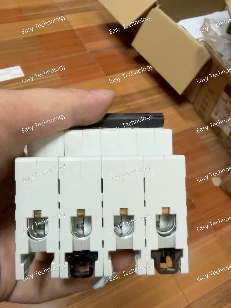
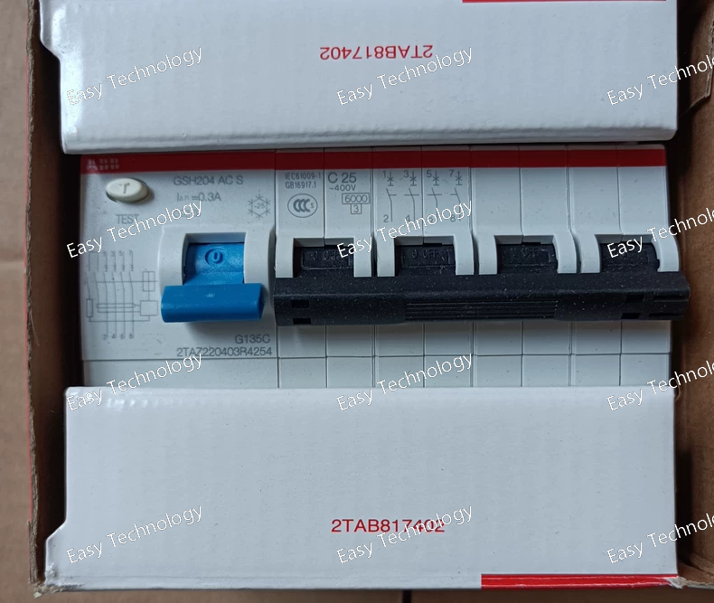
Technical Specifications / Parameters Parameter Specification Manufacturer Order Code 2CDS214001R0251 Catalogue Type S204-C25 Brand / Series ABB S200 Series (System PRO M) Device Type Miniature Circuit Breaker (MCB) Number of Poles 4-Pole (4P) (Breaks all three phases and the neutral) Rated Current (In) 25 A Rated Operational Voltage (Ue) 400 V AC (3P+N~) Rated Insulation Voltage (Ui) 500 V AC Rated Impulse Withstand Voltage (Uimp) 4 kV Tripping Characteristic C Curve (Standard magnetic setting. Instantaneous tripping range: 5In to 10In) Rated Breaking Capacity (Icn) 10 kA (at 400V AC, per IEC/EN 60947-2) Utilization Category A Standards Compliance IEC/EN 60947-2 (Primary, for industrial applications). May also comply with relevant sections of IEC/EN 60898-1 for final distribution. Terminal Type Cage Clamp Terminal (Screwless clamp) Connectable Conductors Solid/Fine-stranded Copper: 1 - 25 mm² Recommended Tightening Torque 2.0 - 2.5 Nm Electrical Endurance ≥ 20,000 cycles (at In) Mechanical Endurance ≥ 20,000 cycles Ambient Temperature Range -25°C to +60°C (for calibration, derating above +40°C) Mounting Snap-on mounting on 35 mm top-hat DIN Rail (EN 60715) Module Width 72 mm (4 Poles) Primary Functions Overload Protection, Short-Circuit Protection Protection Features Trip-free mechanism, clear "ON"/"OFF" visual indication. All poles switch simultaneously. Accessory Compatibility Compatible with the full range of S200 Series System PRO M accessories: auxiliary contacts (OF, SD), alarm contacts (OF), shunt trips, undervoltage releases, etc. Common Approvals CE, CCC, KEMA, etc.
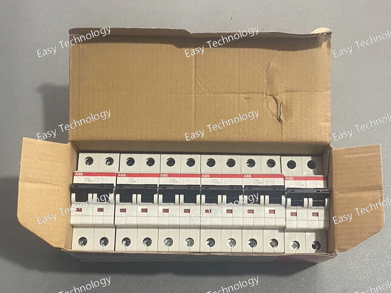
Technical Specifications / Parameters Parameter Specification Manufacturer Order Code 2CDS252001R0487 Catalogue Type S202-K20 Brand / Series ABB S200 Series (System PRO M) Device Type Miniature Circuit Breaker (MCB) Number of Poles 2-Pole (2P) Rated Current (In) 20 A Rated Operational Voltage (Ue) 230/400 V AC Rated Insulation Voltage (Ui) 440 V AC Rated Impulse Withstand Voltage (Uimp) 6 kV Tripping Characteristic K Curve (Specifically designed for high inrush loads. Instantaneous tripping range: ~8In to 12In). Rated Breaking Capacity (Icn) 10 kA (at 400V AC, per IEC/EN 60947-2) Utilization Category A (Instantaneous tripping with no intentional delay for short-circuit) Standards Compliance IEC/EN 60947-2 (Industrial circuit-breaker standard) Terminal Type Cage Clamp Terminal Connectable Conductors Solid/Fine-stranded Copper: 0.75 - 35 mm² (Torque: 3.0 - 3.5 Nm) Electrical Endurance ≥ 20,000 cycles (at In) Mechanical Endurance ≥ 20,000 cycles Ambient Temperature -25°C to +60°C (for calibration, derating above +40°C) Mounting DIN Rail (35 mm, EN 60715) Module Width 36 mm (2 Poles) Primary Functions Overload Protection, Short-Circuit Protection (High Inrush Immune) Protection Features Trip-free mechanism, "ON"/"OFF" visual indication. Accessory Compatibility Compatible with the full range of S200 Series System PRO M accessories: auxiliary contacts (OF, SD), alarm contacts (OF), shunt trips, undervoltage releases, etc. Common Approvals CE, UL 1077 (Supplemental Protector), CCC, etc.
Technical Specifications / Parameters Parameter Specification Manufacturer Type Code SH201-C10 Brand ABB Product Line System PRO M compact® Device Type Miniature Circuit Breaker (MCB) Number of Poles 1-Pole (1P) Rated Current (In) 10 A Rated Operational Voltage (Ue) 230/400V AC Rated Insulation Voltage (Ui) 500V AC Rated Impulse Withstand Voltage (Uimp) 4 kV Tripping Characteristic Curve C Curve (Standard magnetic setting. Instantaneous tripping range: 5In to 10In) Rated Breaking Capacity (Icn) 6 kA (According to IEC/EN 60898-1) Service Breaking Capacity (Ics) 6 kA (100% of Icn) Standards Compliance IEC/EN 60898-1 (Primary standard for household and similar installations) Terminal Type Cage Clamp Terminal (Screwless clamp technology for quick, secure wiring) Connectable Conductors Rigid and Flexible Copper Conductors: 1 - 25 mm² Recommended Tightening Torque 2.0 - 2.5 Nm Electrical Endurance ≥ 20,000 making and breaking operations at rated current (In) Mechanical Endurance ≥ 20,000 operations Ambient Temperature Range (for calibration) -25°C to +55°C Mounting Snap-on mounting on 35 mm symmetrical top-hat DIN Rail (EN 60715) Module Width 18 mm (1 Pole = 1 module) Primary Protective Functions Overload (Thermal) Protection, Short-Circuit (Electromagnetic) Protection Auxiliary Functions Clear "ON" (I) and "OFF" (0) indication. Compatible with a range of System PRO M accessories such as auxiliary contacts (SH-AA) and alarm contacts (SH-AL). Common Approvals & Marks CE, CCC, IMQ, KEMA, etc. (Varies by target market) Housing Material Flame-retardant thermoplastic (Polycarbonate blend)
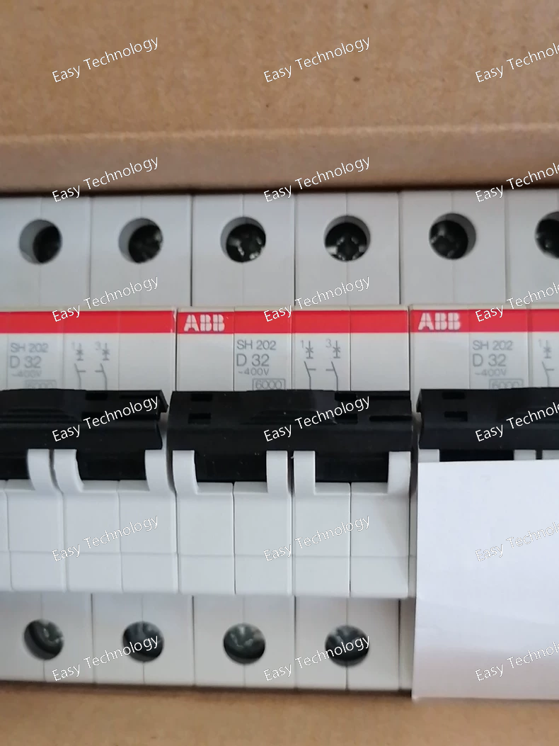
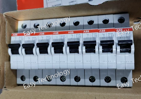
Technical Specifications / Parameters Parameter Specification Manufacturer P/N (Order Code) 2CDS212001R0321 Catalogue Type SH202-D32 Brand ABB Product Line System PRO M compact® Device Type Miniature Circuit Breaker (MCB) Number of Poles 2-Pole (2P) Rated Current (In) 32 A Rated Operational Voltage (Ue) 230/400 V AC Rated Insulation Voltage (Ui) 500 V AC Rated Impulse Withstand Voltage (Uimp) 4 kV Tripping Characteristic Curve D Curve (Instantaneous tripping range: 10In to 14In). High magnetic setting for inrush tolerance. Rated Breaking Capacity (Icn) 6 kA (IEC/EN 60898-1) Service Breaking Capacity (Ics) 6 kA (100% of Icn) Standards Compliance IEC/EN 60898-1, IEC/EN 60947-2 Terminals Cage Clamp Terminal Connectable Conductors Rigid/Flexible Copper: 1 - 25 mm² Tightening Torque 2.0 - 2.5 Nm Electrical Endurance ≥ 20,000 operations (at In) Mechanical Endurance ≥ 20,000 operations Ambient Temperature -25°C to +55°C (for calibration) Mounting DIN Rail (35 mm symmetrical rail, EN 60715) Module Width 36 mm (2 Poles) Primary Functions Overload Protection, Short-Circuit Protection (High Inrush Type). Auxiliary Functions Clear "OFF" (0) indication. Compatible with System PRO M accessories: auxiliary switches (SH-AA), alarm switches (SH-AL), etc. Markings & Approvals CE, CCC, KEMA, etc. (Market dependent)
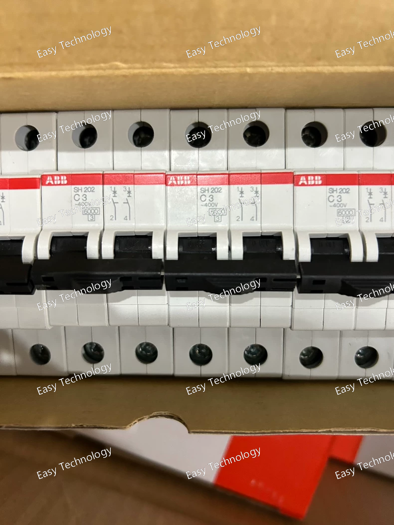
Technical Specifications / Parameters Parameter Specification Manufacturer P/N SH202-C3 Brand ABB Product Line System PRO M compact® Device Type Miniature Circuit Breaker (MCB) Number of Poles 3-Pole (3P) Rated Current (In) 2 A Rated Operational Voltage (Ue) 230/400 V AC Rated Insulation Voltage (Ui) 500 V AC Rated Impulse Withstand Voltage (Uimp) 4 kV Tripping Characteristic Curve C Curve (Instantaneous tripping range: 5In to 10In) Rated Breaking Capacity (Icn) 6 kA (IEC/EN 60898-1) Service Breaking Capacity (Ics) 6 kA (100% of Icn) Standards Compliance IEC/EN 60898-1 (Primary), IEC/EN 60947-2 (for certain declarations) Terminals Cage Clamp Terminal Connectable Conductors Rigid/Flexible Copper: 1 - 25 mm² Tightening Torque 2.0 - 2.5 Nm Electrical Endurance ≥ 20,000 operations (at In) Mechanical Endurance ≥ 20,000 operations Ambient Temperature -25°C to +55°C (for calibration) Mounting DIN Rail (35 mm symmetrical rail, EN 60715) Module Width 54 mm (3 Poles) Primary Functions Overload Protection, Short-Circuit Protection Auxiliary Functions Clear "OFF" (0) indication. Compatible with a wide range of accessories: auxiliary switches (SH-AA), alarm switches (SH-AL), undervoltage releases (SH-SD), shunt trips (SH-SB), etc. Markings & Approvals CE, IMQ, CCC, KEMA, etc. (Market dependent)
Technical Specifications / Parameters Parameter Specification Manufacturer P/N 2TAZ133110R0401 Brand ABB Product Line Push-button & Indicating Light System Type Selector Switch Head / Operator Module Front Bezel Diameter 22.5 mm (Standard) Key Feature Integral Neon Indicator Indicator Color Red Operator Type Key-Operated (Key can be removed in certain positions) Contact Configuration None (This is the operator only. Electrical contacts are provided by a separate, attachable contact block.) Mechanical Life > 1,000,000 cycles (for the operator mechanism; dependent on assembly) Electrical Rating Determined solely by the attached contact block. This head does not carry an independent electrical rating. Front Panel Protection IP65 (Dust-tight and protected against water jets) when correctly mounted. Material (Front) High-grade thermoplastic (e.g., Polyamide) Mounting Snap-fit installation into a 22.5mm panel cutout from the front. Compatibility Designed to mate with standard ABB 22.5mm contact blocks and mounting frames (e.g., from CP-S, XB4, or equivalent series). Function Used to create 2 or 3-position selector switches, key-operated push-buttons, or emergency stop commands with indication. Typical Application Industrial control panels, machine automation, process control systems – for mode selection, motor control, system enable/disable functions.
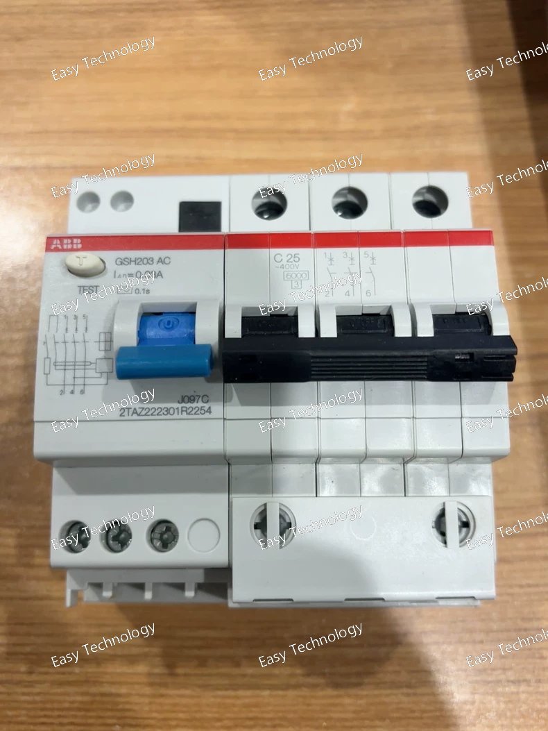
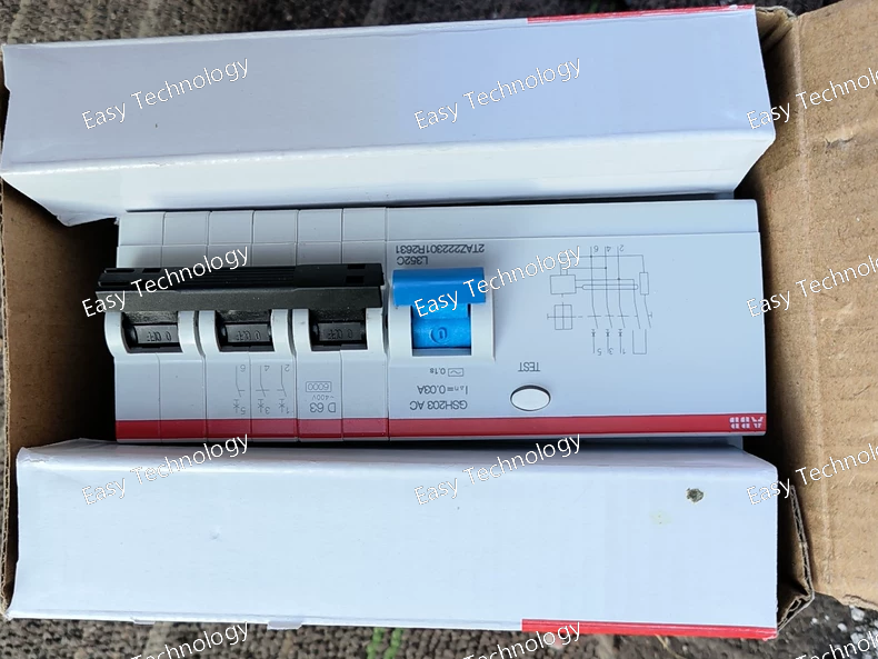
Technical Parameters Parameter Category Specification Notes Base Device GSH204 400A frame high-performance contactor. Main Circuit Ratings • Rated Operational Current (Ie) 400 A (at AC-3, 400V) Standard rating for the GSH204 frame. • Rated Operational Voltage (Ue) Up to 690 V AC Handle / Actuator -C25 Front-mounted rotary handle. The 25 is a specific handle type code, likely indicating a particular design with padlocking capability and clear ON/OFF indication. Control Circuit Protection /0.3 Integrated 0.3A (300mA) fuse for the control coil circuit (terminals A1-A2). • Key Difference: This is ten times the rating of the common /0.03 (30mA) fuse. Control Coil Fuse (/0.3) Core Feature with Higher Rating • Purpose To protect the external control power source from sustained overloads or short-circuits in the contactor's coil circuit, while providing a higher trip threshold. • Rating 300 mA, gG or similar. • Application Rationale Used when: 1. The control circuit has longer wiring runs with higher inherent capacitance/leakage. 2. The coil inrush current is higher (e.g., for large DC coils or certain AC coils). 3. To coordinate with upstream protection and avoid nuisance tripping from transient currents. 4. The control source (e.g., a larger transformer or dedicated power supply) can safely support this higher fault current level until the fuse clears. Control Coil IMPORTANT: The model GSH204-C25/0.3 does not specify the coil voltage or type (AC/DC). This must be specified separately in the full order code (e.g., GSH204 A400 -C25/0.3 for a 400V AC coil). Utilization Categories AC-3, AC-4, AC-1 For very large motor and resistive load switching. Switching Capacity • Making Capacity (Icm): Very high, typically 4000A or more (peak). • Short-circuit Withstand: Requires backup protection. Mechanical Life ≥ 10 million operations Electrical Life (AC-3) ≥ 1.0 million operations at full rated current Auxiliary Contacts Modular blocks can be added. Mounting Heavy-duty foot mounting for panel installation. Dimensions & Weight Large and heavy (e.g., >15 kg).
Technical Specifications | Parameter Category | Specification / Inference | | :--- | :--- | :--- | | Product Type | Switched-Mode DC/DC Converter | | Product Family | ABB CP Series (Control Power). 2TAZ is the definitive family prefix. | | Standard | IEC 62368-1, IEC 61204-7 | | Input Voltage (Uin) | Defined by 222301. • This code segment is identical to the previously analyzed 2TAZ222301R2631. • Therefore, the input voltage is highly likely the same: 24 V DC nominal (with a wide range, e.g., 18-36 V DC). This module is designed to be powered from a 24V DC system. | | Output Voltage (Uout) | Likely 24 V DC. The code R2254 is interpreted as: • R: Regulated output. • 22: Likely a sub-series or product variant code. As with R2631, the actual output voltage is most probably the industry-standard 24V DC. • 54: Likely indicates the output current rating. In common encoding, 54 could correspond to 5.4 A or be coded for 5.0 A (where 5 = 5A, 4 = version/check). | | Output Current (Iout) | Likely 5.0 A or 5.4 A (Inferred from 54 in R2254). This is a higher current output compared to the R2631 (~3A) model within the same 222301 input family. | | Output Power (Pout) | Approximately 120W - 130W (If 24V @ 5A/5.4A: 24V * 5A = 120W). | | Output Characteristics | • Precisely regulated voltage. • Protections: Short-circuit, overload, overvoltage, overtemperature. • Isolation: Galvanic isolation between input and output (typically ≥ 3 kV). • Low output ripple. | | Efficiency | > 85% (typical). | | Mounting | 35 mm DIN Rail (EN 60715). | | Terminations | Screw-clamp terminals capable of handling the higher output current. | | Cooling | Natural convection (fanless) or possibly a small fan, depending on thermal design. | | Operating Temperature | -25°C to +70°C | | Protection Degree | IP20. | | Status Indication | LED(s) for input power and output status. | | Safety Approvals | CE, UL, cULus. | | Typical Application | Used in control systems where the primary available DC source is 24V, but a higher-power, isolated 24V output is required. Common in: • Powering a large PLC system with multiple I/O racks from a 24V battery-backed bus. • Supplying a group of protective relays and meters in a substation automation cabinet. • Creating a dedicated, clean 24V bus for sensitive instrumentation, isolated from a noisy main 24V supply. |
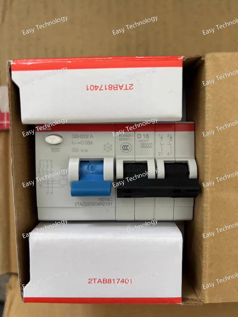
Technical Parameters Parameter Category Specification Notes Base Device GSH202 AC 200A frame high-performance contactor. AC indicates an AC-operating coil, but the exact voltage (e.g., 230V) is not specified here and must be provided as a separate part of the full order code. Main Circuit Ratings • Rated Operational Current (Ie) 200 A (at AC-3, 400V) • Rated Operational Voltage (Ue) Up to 690 V AC Mounting/Accessory Package -D16 Specific mechanical/accessory code. In GSH series coding: • D often denotes a specific mounting style, terminal configuration, or a version without a prominent front manual handle (compared to C codes). It may indicate a flush or compact design intended primarily for electrical operation. • 16 is a variant code, likely specifying details like included auxiliary contacts, terminal types, or mounting bracket style. Critical Special Feature /0.03 Integrated 0.03A (30mA) fuse for the control coil circuit (terminals A1-A2). Control Coil Fuse (/0.03) Core Protective Feature • Purpose To protect the external control power source from damage in case of a short circuit in the contactor's coil or its wiring. Safeguards PLC outputs, relay contacts, or small control transformers. • Rating 30 mA, gG or similar. • Location Integrated within the contactor assembly, often in a dedicated, accessible compartment. Control Coil AC (type specified). Coil voltage is a separate, mandatory specification. Example full order code: GSH202 A230 -D16/0.03 Utilization Categories AC-3, AC-4, AC-1 For motor and resistive load switching. Switching Capacity • Making Capacity (Icm): ~2000 A (peak). • Short-circuit Withstand: Requires backup fuse/circuit breaker. Mechanical Life ≥ 10 million operations Electrical Life (AC-3) ≥ 1.0 million operations at full rated current (200A) Typical Inclusions (Interpretation of -D16) Likely includes a basic set of built-in auxiliary contacts (e.g., 1NO+1NC) for status feedback. It likely does NOT include a front manual rotary handle for local operation. Must be confirmed with specific documentation for -D16. Mounting Standard foot mounting or as defined by the D package. Operation Primarily electrical via its coil. Lacks a manual operator handle.
Technical Specifications | Parameter Category | Specification / Inference | | :--- | :--- | :--- | | Product Type | Switched-Mode DC/DC Converter | | Product Family | ABB CP Series. 2TAZ is the characteristic family prefix. | | Standard | IEC 62368-1, IEC 61204-7 | | Input Voltage (Uin) | Defined by 222301. This is a different input code from previously seen 220301 and 220406. This strongly suggests a different nominal input voltage. • Probable Interpretation: 2223 may correspond to a 24 V DC nominal input system (e.g., with a wide range of 18-36 V DC). This is a common voltage for systems powered by small battery banks or low-voltage DC supplies. • Alternative: Could be a variant of 48V DC. Official verification is essential. | | Output Voltage (Uout) | Likely 24 V DC. The code R2631 is interpreted as: • R: Regulated output. • 26: Likely a sub-series or product variant code. The actual output voltage is most probably the industry-standard 24V DC. • 31: Likely indicates the output current rating. In common encoding, 31 could correspond to 3.1 A or be coded for 3.0 A (where 3 = 3A, 1 = version). | | Output Current (Iout) | Likely 3.0 A or 3.1 A (Inferred from 31 in R2631). This positions it between the R2321 (~2A) and R2504 (~4A) models in terms of power. | | Output Power (Pout) | Approximately 72W - 75W (If 24V @ 3A/3.1A: 24V * 3A = 72W). | | Output Characteristics | • Precisely regulated voltage. • Protections: Short-circuit, overload, overvoltage. • Isolation: Galvanic isolation. • Low ripple and noise. | | Efficiency | > 85% (typical). | | Mounting | 35 mm DIN Rail (EN 60715). | | Terminations | Screw-clamp terminals. | | Cooling | Natural convection (fanless). | | Operating Temperature | -25°C to +70°C | | Protection Degree | IP20. | | Status Indication | LED for "Power On". | | Safety Approvals | CE, UL, cULus. | | Typical Application | Used in control systems where the primary available DC source is 24V (e.g., from a battery or another power supply), and a separate, isolated 24V output is needed for critical loads. Common in: • Creating an isolated 24V bus from a non-isolated 24V source to prevent ground loops and noise interference. • Powering devices in a 24V DC system that require a cleaner or separately derived source. |
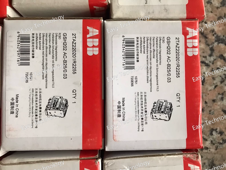
Technical Parameters Parameter Category Specification Notes Base Device GSH202 200A frame high-performance contactor. Variant/Accessory Code B25 This suffix is critical but its meaning is not generic. In ABB's GSH coding: • B likely indicates a specific "Basic" version or a version without a front-mounted rotary handle (like -Cxx codes have). It may imply a flush-mounted design intended for operation only via its electrical coil. • 25 is likely a performance or accessory package code. It could indicate a standard set of included items, such as: - A specific number of built-in auxiliary contacts (e.g., 1NO+1NC). - Undervoltage release (MN) or Shunt Trip (MX) pre-installed. - Specific terminal type or connection style. Rated Operational Current (Ie) 200 A (at AC-3, 400V) Standard rating for the GSH202 frame. Rated Operational Voltage (Ue) Up to 690 V AC Control Coil NOT SPECIFIED. The B25 code does not define the coil. This is a major point of ambiguity. The contactor requires a coil, typically specified as a separate part of the order code (e.g., GSH202 A230 B25 for a 230V AC coil). Must be verified on the device nameplate or in the complete ordering documentation. Utilization Categories AC-3, AC-4, AC-1 For motor, resistive, and mixed loads. Switching Capacity • Rated Making Capacity (Icm): ~2000 A (peak). • Short-circuit Withstand: Requires backup protection (fuse/circuit breaker). Mechanical Life ≥ 10 million operations Electrical Life (AC-3) ≥ 1.0 million operations at full rated load (200A) Common Inclusions (Interpretation of B25) Likely includes a minimal set of built-in auxiliary contacts (e.g., 1 NO + 1 NC) for basic feedback. It likely does NOT include a manual operator handle, electric charging motor, or other advanced accessories by default. This must be confirmed with the specific datasheet for GSH202 B25. Mounting Standard foot mounting for panel installation. Operation Purely electrical. Lacks a manual rotary handle for local operation. Must be operated by energizing/de-energizing its coil.
 TEL: Grace +86 13600179521
  Mail: info@hongkongeasy.com jilineasyyi@outlook.com
 Q Q:615739355
 ADDRESS:Unit 12, 20th Floor, Good View Commercial Centre, 2-16 Garden Street, Mong Kok, Hong Kong
 whats app


