
Industrial Controller
All product are in stock,guaranteed delivery within 3-7 days.


PRODUCT
PICTURE
BRAND
DESCRIBE
STOCK
DOWNLOAD
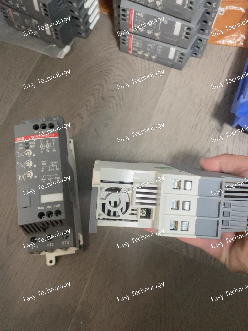
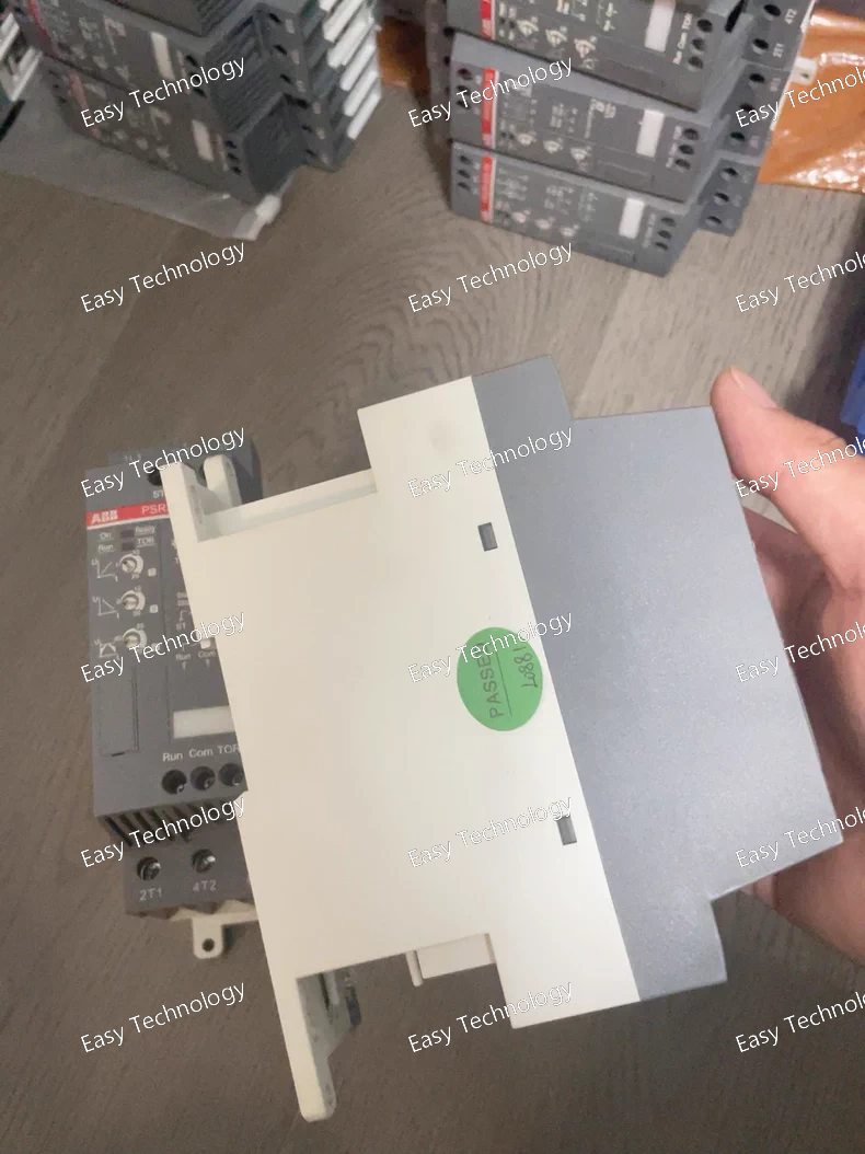
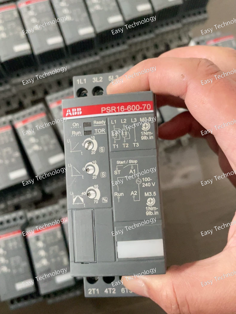
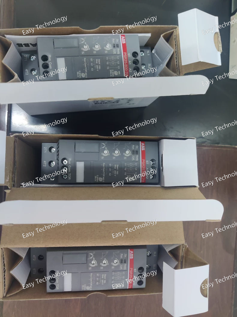
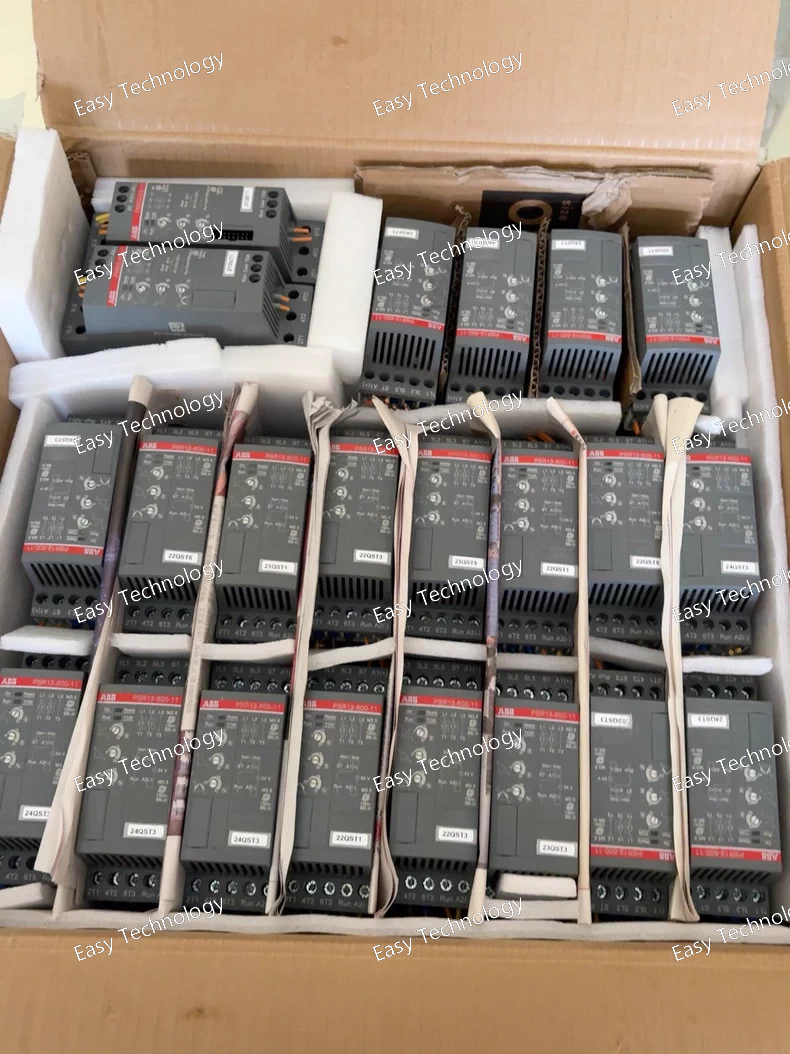
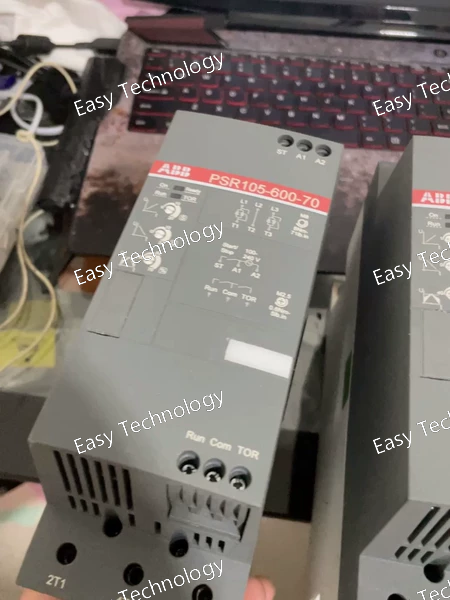
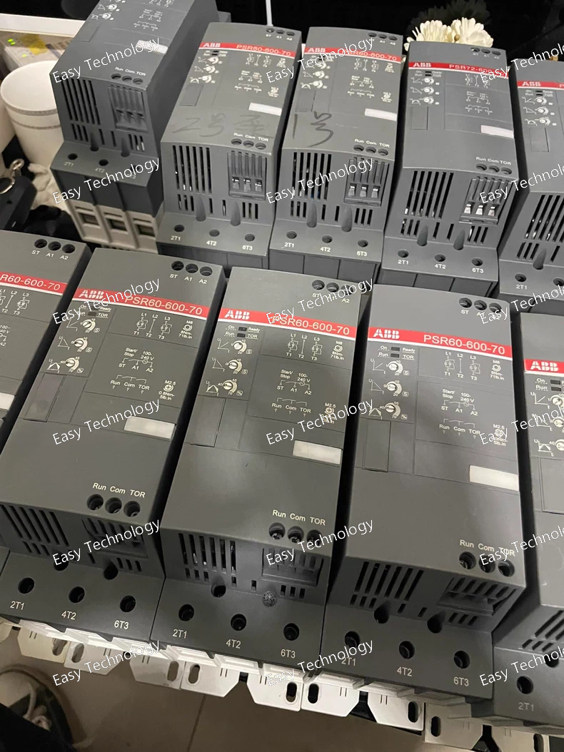
Technical Parameters Parameter Category Specification Product Family / Type Digital Combined Motor Starter Relay (Electronic Overload Relay + Controller) Standard Compliance IEC/EN 60947-4-1, IEC/EN 60947-5-1 Rated Auxiliary Supply Voltage (Us) 48 - 250 V DC / 48 - 240 V AC, 50/60 Hz (Auto-ranging, suffix -70) Rated Motor Current (Iu) Adjustable via display, typical range 0.1A - 600A (dependent on connected current sensors). The -600- indicates compatibility with 1A CTs, but the relay itself covers a wide range via settings. Current Sensors Requires external Current Transformers (CTs) or Rogowski Coils. Standard options: 1A or 5A secondary CTs. Core Protection Functions • Thermal Overload (49) Digital thermal replica with separate heating/cooling curves. Settings: Iu (FLC), Trip Class (5…40), Ambient Temp compensation. • Phase Unbalance (46) Protection based on negative sequence current. • Phase Loss (Fuse Blow) Detection of a missing phase. • Earth Fault (50N) Residual current protection (requires external Core Balance CT). • Locked Rotor / Stall (48) Short-time pick-up protection. • Underload (37) • Jam (Current Increase) • Number of Starts / Time Between Starts Programmable start inhibition. Control & I/O Functions • Contactor Control Built-in logic to directly command a bypass contactor (for start/stop). This is a key feature that replaces separate logic. • Digital Inputs 4 programmable inputs (e.g., Start, Stop, Reset, Remote Set). • Output Relays 4 programmable relays (Changeover contacts). Typically assigned to: Ready, Running, Alarm, Trip, or Control. Human-Machine Interface (HMI) • Display 2-line, 16-character backlit LCD for settings, Iu value, motor current, thermal capacity %, and fault messages. • Indicators 6 LEDs: PWR, RUN, TRIP, ALARM, COMM, and a multifunctional LED. • Navigation 3 buttons (Up, Down, Select/Enter) for local programming. Monitoring & Diagnostics • Measured Values Phase currents (L1, L2, L3), ground current, thermal capacity %, motor status. • Fault Memory Stores last fault type (e.g., overload, unbalance, phase loss). Communication (Optional) Can be equipped with a plug-in communication module: Profibus DP, Modbus RTU, or DeviceNet. Operating Temperature -25°C to +60°C Storage Temperature -40°C to +85°C Mounting Mounts directly on DIN rail (35mm). Physically designed to be combined with ABB contactors (e.g., AF series) for a compact starter assembly. Protection Rating IP20 Dimensions (W x H x D) Approx. 90 mm x 140 mm x 120 mm (Variable based on configuration). Key Design Feature "Bypass" Operation: After starting the motor, the relay switches the current path from its internal electronics to a parallel-connected power contactor, reducing internal heat and power loss. This is central to its "combined starter" design.
Technical Parameters Parameter Category Specification Product Family / Type Compact Multifunction Protection Relay Standard Compliance IEC 60255, IEC 60947-1 Rated Auxiliary Supply Voltage (Us) 48 - 250 V DC / 48 - 240 V AC, 50/60 Hz (Auto-ranging, suffix -70) Rated Current Input (In) 1 A AC (This is defined by the -600- in the type code). Configurable Relay Functions Set via 8-position DIP switch on front: • Three-phase overcurrent (I>) • Two-phase overcurrent (I>) • Single-phase overcurrent (I>) • Sensitive earth-fault (I0>) • Three-phase overcurrent + Earth-fault (I> + I0>) Protection Characteristics • Operate Value Range Phase: 0.5 - 5.0 x In (in 8 steps) Earth: 0.02 - 0.5 x In (in 8 steps) • Time Delay Definite Time (DT). Adjustable via potentiometer: 0.06 - 3.0 seconds. • Reset Time Approx. 60 ms (Instantaneous reset). Output Contacts • Trip Relay 1 Changeover (CO) contact (SPDT). • Rated load: 8 A, 250 V AC / 5 A, 30 V DC. • Signal Relay 1 Changeover (CO) contact (SPDT). • Can be configured for trip repetition or as a separate alarm. Binary Inputs 1 programmable input. Can be used for Remote Reset or Blocking. Indications 3 LEDs: - Green (PWR): Power ON. - Yellow (ALARM): Pre-alarm or start signal. - Red (TRIP): Protection has operated. Measurement Monitors phase currents and calculates maximum value for protection. No local display of numeric values. Operate Time Accuracy ±5% of set value or ±30 ms, whichever is greater. Burden < 0.2 VA per current input at In. Electrical Durability Output contacts: ≥ 100,000 mechanical operations; ≥ 10,000 electrical operations at rated load. Isolation 4 kV RMS between all circuits (supply, current inputs, outputs). Operating Temperature -25°C to +55°C Storage Temperature -40°C to +85°C Mounting Standard DIN rail (35mm). Housing Material Self-extinguishing thermoplastic (Polyamide). Protection Rating IP40 (front), IP20 (terminals). Dimensions (W x H x D) Approx. 70 mm x 122 mm x 116 mm (4 module width = 70mm). Weight Approx. 0.45 kg. Certifications CE, cULus, RoHS.
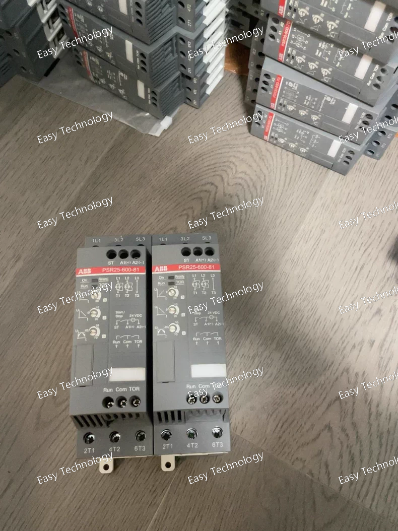
Technical Parameters Parameter Category Specification Product Family / Type Self-Powered Three-Phase Current Monitoring Relay Function Protection against: Phase Loss, Phase Reversal, Current Asymmetry (Unbalance). Standard Compliance IEC 60947-1, IEC 60947-5-1 Power Supply Self-powered from the monitored current transformers (CTs). No external auxiliary voltage required. Rated Current Input (In) 1 A AC (This is defined by the -600- in the type code. 600 = 1A; 500 = 5A). Operating Range 0.1 A to 1.3 A AC. Frequency 50 / 60 Hz. Monitoring Functions & Settings • Phase Loss Detection Detects if any phase current falls below the threshold setting. • Phase Asymmetry (Unbalance) Detects imbalance between phase currents. Adjustable tripping threshold (e.g., 20% to 70% of asymmetry). • Phase Sequence Monitors for correct phase rotation (e.g., L1-L2-L3). Trips on reversal. • Threshold Setting (I<) Adjustable via rotary switch (typically 0.15 - 0.95 x In) to define the minimum current level. • Response Time Fixed, typically around 0.1 to 1 second. Output Contact • Type 1 Changeover (CO) contact (SPDT: 1 NO + 1 NC). • Rated Operational Current (Ie) 6 A AC-15 / 0.5 A DC-13. • Utilization Category AC-15: 230V, 6A; DC-13: 24V, 0.5A. Binary Input 1 Reset/Start Input (Terminal A1). A voltage pulse (24-240V AC/DC) is required to close the output relay after a fault or power-up. Indications 2 LEDs: - Green (On) : Power OK, correct phase sequence, currents above threshold. - Red (Trip) : Fault condition (Phase Loss, Reversal, or Asymmetry). Connection Screw-clamp terminals for: - 3 Phase Current Inputs (L1, L2, L3). - Output Contact (13, 14, 23). - Reset Input (A1, A2). Electrical Life ≥ 100,000 cycles (at rated load). Isolation Reinforced insulation between current circuits, output contact, and reset input. Operating Temperature -25°C to +55°C Storage Temperature -40°C to +85°C Mounting Standard DIN rail (35mm TS35/7.5 or 15mm). Housing Material Self-extinguishing thermoplastic (Polyamide PA 6.6). Protection Rating IP20 (front), IP40 (housed in appropriate enclosure). Dimensions (W x H x D) Approx. 22.5 mm x 100 mm x 112 mm (1 Module width = 22.5mm). Weight Approx. 0.15 kg. Certifications CE, cULus, RoHS.
Technical Parameters Category Specification Product Series PSR - Digital Protection Relay Device Type Modular Motor Management Relay / Intelligent Motor Protector Key Standards IEC 60255, IEC 60947, ANSI/IEEE C37.90, IEC 61850 (with module) Rated Auxiliary Supply 48–250 V DC / 48–240 V AC, 50/60 Hz (Auto-sensing, suffix -70) Current Input (CT Secondary) 1 A or 5 A (Configurable, 1 A nominal shown by -600- code) Measurement Accuracy Current: ±1% of reading; Voltage: ±0.5% of reading; Power: ±2% of reading Core Protection Functions • Thermal Model (49) Dual thermal models (running/stationary), adjustable overload curve, thermal alarm (e.g., 95%), trip (100%). • Short Circuit (50/51) Phase instantaneous (I>) & time-delayed overcurrent (I>>) with IDMT/DT curves. • Stall / Prolonged Start (48/14) Separate start thermal model, adjustable stall time setting. • Phase Unbalance (46) Negative sequence protection (% of Iavg), trip delay. • Earth Fault (50N/51N/67N) Residual (calculated) or core-balance (measured) current. Instantaneous or time-delayed, directional option. • Underload / Jam (37) Minimum current or power protection. • Under/Overvoltage (27/59) Two-stage with timers. • Under/Overfrequency (81) • Restart Inhibit / Starts per Hour Programmable number of starts and minimum time between starts. Control & Logic • Integrated PLC Engine Graphical logic editor (PSRsoft) for custom control sequences, interlocks, timers, counters. • Pre-defined Control Profiles Direct-on-Line (DOL), Reversing, Star-Delta, Soft Starter, Pump, Valve, etc. Inputs/Outputs (Base + Expandable) • Binary Inputs (Discrete Inputs) 6 x 24-250V DC/AC programmable inputs (base unit). Expandable via I/O modules. • Output Relays 5 x changeover (CO) relays (base unit: Trip, 2x Alarm, 2x Programmable). Expandable. • Analog Inputs Optional module for 0/4-20 mA or PT100 temperature inputs. Human-Machine Interface • Display High-contrast graphical LCD with backlight (128 x 64 pixels). • Indicators 10+ multi-color LEDs (Power, Ready, Run, Trip, Alarm, Comms, etc.). • Navigation 6 tactile keys (Menu, Up, Down, Enter, Escape, Reset). Monitoring & Diagnostics • Measured Values Il1, Il2, Il3, Iavg, I_neg, I_earth, Vll, Vln, Freq, P, Q, S, PF, kWh, kVARh, Thermal Capacity, Starts Count, Run Hours. • Event Recorder 512 time-stamped events (trips, alarms, commands, system events). • Oscillography (Disturbance Recorder) 8 analog channels (currents/voltages), pre- and post-trigger recording. Communication • Front Port USB for local configuration (PSRsoft) and event log extraction. • Rear Communication Slots 2 independent slots for plug-in modules: - Protocols: Modbus RTU (RS485), Profibus DP, DeviceNet, IEC 61850, Modbus TCP/IP (Ethernet). - I/O Expanders: Additional digital/analog I/O modules. Clock & Synchronization Internal real-time clock; optional IRIG-B or SNTP (via comm module) for time sync. Environmental • Operating Temperature -25°C to +70°C • Storage Temperature -40°C to +85°C • Relative Humidity 5% to 95%, non-condensing • Protection Rating IP40 (front), IP20 (terminals) Mechanical • Housing Self-extinguishing plastic (UL94 V-0), modular design. • Mounting Panel-mounted (flush), requires cutout. • Dimensions (W x H x D) 144 mm x 144 mm x 122 mm (6 TE width). • Weight Approx. 1.2 kg (base unit). Certifications CE, UL, cUL, DNV GL, ATEX (optional), IECEx (optional).
Parameter Category Specification Product Family / Type Numerical Motor Protection and Control Relay (Motor Management System) Standard Compliance IEC 60255, IEC 60947-1, -4, -5, IEC 61850 (with module) Rated Auxiliary Supply Voltage (Us) 48 - 250 V DC / 48 - 240 V AC, 50/60 Hz (Auto-ranging, -70 suffix) Motor Current Input (CT Secondary) 1 A or 5 A (Configurable) Protection Functions • Thermal Overload (49) Dual (separate) thermal models for Running and Stopped states. Includes cooling time constants, service factor, and bi-metallic compensation. • Short Circuit / Instant OC (50) Instantaneous phase and earth-fault. • Start-up Supervision / Stall (48/14) Anti-stall protection with separate thermal model for starts. Start time monitoring. • Phase Unbalance & Loss (46) Negative sequence current protection with high sensitivity. • Earth-Fault (50N/51N/67N) Directional or Non-directional, residual or core balance measurement. Multiple stages. • Underload / Jam (37) Underpower or mechanical jam protection. • Under/Overvoltage (27/59) • Under/Overfrequency (81) • Number of Starts Control of successive starts and restart inhibition time. Control & Logic Features • Integrated PLC Programmable logic (PSRsoft software) for custom control sequences, interlocking, and automation. • Standard Control Profiles Direct-on-line (DOL), Star-Delta, Soft Starter, Pump, Valve control, etc. • I/O Expansion Modular slots for additional digital/analog input & output modules. Measured & Calculated Values Phase & ground currents, voltages, frequency, power (P, Q, S), power factor, energy, motor thermal capacity, starts counter, running hours. Human-Machine Interface (HMI) Large backlit graphical LCD with status, measurements, bar graphs, event log. 6 navigation keys. 9+ LED indicators. Event Logging & Oscillography Stores time-tagged fault records, alarms, operations. Optional disturbance recorder (oscillography) for pre-/post-fault current waveforms. Output Contacts • Base Unit Relays Typically 4-6 programmable changeover (CO) relays (Trip, Alarm, Control outputs). • Expandable Via additional I/O modules. Binary Inputs • Base Unit Typically 4-6 programmable digital inputs. • Expandable Via additional I/O modules (including analog inputs). Communication (Standard & Optional) • Standard Port RS485 (Modbus RTU protocol). • Plug-in Modules Supports IEC 61850, Profibus DP, DeviceNet, Modbus TCP/IP (Ethernet), CANopen. Operating Temperature -25°C to +60°C (-13°F to +140°F) Housing & Mounting Modular plastic case for panel mounting. Width varies with configuration (base unit + modules). Dimensions (Base Unit, W x H x D) Approximately 144mm x 144mm x 122mm (6TE width).
Parameter Category Specification Product Family / Type Numerical Motor Protection Relay Standard Compliance IEC 60255, IEC 60947-1, -4, -5 Rated Auxiliary Supply Voltage (Us) 24 - 48 V DC Motor Current Input (CT Secondary) 1 A or 5 A (Hardware selectable via DIP switch) Protection Functions • Thermal Overload (49) Based on motor FLC setting. Tripping characteristic matches motor thermal capacity. Separate alarm and trip settings. Cool/Start inhibit. • Short Circuit / Instant OC (50) High-set instantaneous overcurrent for short-circuit protection. • Start-up Supervision / Stall (48/14) Separate thermal model for start-up. Protects against locked rotor and prolonged starts. • Phase Unbalance / Loss (46) Protects against negative sequence currents due to phase unbalance or loss. • Earth-Fault (50N/51N) Residual current measurement (via core balance CT or derived). Instantaneous or time-delayed. • Undercurrent (37) Optional protection against pump run-dry or loss of load. • Number of Starts Programmable restriction on successive starts to prevent overheating. Setting & Configuration • Front Interface Rotary switch for Ir (FLC), Isd (SC), t6x (stall time) selection. DIP switches for Ie (EF), tE (EF delay), Iu (unbalance), etc. • PC Software Optional "PSRsoft" software for detailed configuration, monitoring, and diagnostics via USB port. Measured Values Phase currents (IL1, IL2, IL3), earth-fault current, thermal capacity used (%) Output Contacts • Trip Relay (CO) 1 Changeover contact, for tripping the circuit breaker/contactor. • Signal Relay 1 (CO) 1 Changeover contact, typically pre-assigned to Thermal Alarm. • Signal Relay 2 (CO) 1 Changeover contact, programmable for various alarms (e.g., Unbalance, Earth Fault). • Binary Inputs 2 inputs: Programmable for functions like Reset, General Alarm, Undercurrent Enable. Communication (Optional) Can be equipped with plug-in communication modules for: Modbus RTU (RS485), Profibus DP, DeviceNet. Human-Machine Interface (HMI) 7 LED indicators (Ready, Trip, Alarm, Start, Running, Comms, General Alarm). Rotary switch and DIP switches for settings. Motor Data Memory Stores thermal state for motor restart after power loss (with optional supercapacitor). Operating Temperature -20°C to +60°C (-4°F to +140°F) Housing & Mounting Compact, modular plastic case for DIN rail mounting (standard TS35 rail). Dimensions (W x H x D) Approximately 70mm x 125mm x 121mm (single module width).
Parameter Category Specification Product Family / Type Numerical Feeder Protection Relay Standard Compliance IEC 60255, IEC 61850 (with communication module), ANSI/IEEE C37.90 Rated Auxiliary Supply Voltage (Us) 48 - 250 V DC / 48 - 240 V AC, 50/60 Hz (Auto-ranging) Current Input (CT Secondary) 1 A or 5 A (Hardware selectable) Voltage Input (VT Secondary) 100 / 110 / 120 / 200 / 220 / 230 / 240 / 380 / 400 / 415 / 480 V AC (Phase-to-Phase) Protection Functions • Phase Overcurrent Two stages: Instantaneous (I>) & Time-delayed (I>>) with multiple IDMT/DT curves. • Earth-Fault Current Directional or Non-directional. One stage (I0>>) with IDMT/DT curves. Highly sensitive setting range. • Voltage Protection Two stages each for Undervoltage (U<) & Overvoltage (U>). Definite time delay. • Thermal Overload (49) Single time constant model, alarm and trip stages. Setting Ranges (Typical) • Phase Current 0.1 - 15.0 x In (In steps) • Earth Current 0.01 - 3.00 x In (In steps) • Voltage 10 - 130% of Un (Un = Rated VT input) Measured Values (Display) IL1, IL2, IL3, I0 (earth), UL1, UL2, UL3, Uavg, Freq, P, Q, S, PF, etc. Output Contacts • Trip Relays 3 Changeover (CO) contacts, high-breaking capacity. • Signal Relays 3 Changeover (CO) contacts for alarms/signaling. • Binary Inputs 4 or 5 programmable, for external control/blocking. Communication (Optional) Plug-in modules for: IEC 61850, Modbus RTU (RS485), Profibus DP, IEC 60870-5-103. Human-Machine Interface (HMI) Backlit graphical LCD, 6 navigation keys, 6 LED indicators (Ready, Trip, Alarm, etc.). Event Logging Stores time-tagged fault records, alarms, and operations. Operating Temperature -25°C to +70°C (-13°F to +158°F) Housing & Mounting Compact, modular plastic case. Suitable for flush mounting on panel door or DIN rail. Dimensions (W x H x D) Approximately 105mm x 145mm x 122mm (specific to case style).
Technical Parameters: Parameter Category Specification Standard Compliance IEC 60255, IEC 60870-5-103 (with comm. module) Rated Auxiliary Voltage (Us) 48 - 250 V DC / 48 - 240 V AC (wide range) Rated Frequency (fn) 50 / 60 Hz Current Input (CT Secondary) 1 A or 5 A (selectable) Overcurrent Protection • Phase Stages 2 stages: Instantaneous (I>) & Time-delayed (I>>) • Earth-Fault Stage 1 stage: Time-delayed (I0>>) • Setting Ranges Phase: Typically 0.1 - 1.2 x In (I>) & 1 - 15 x In (I>>) in steps. Earth: Typically 0.02 - 1.2 x In (sensitive). (Refer to official manual for exact ranges.) • Time Curves Definite Time (DT), Inverse Definite Minimum Time (IDMT) per IEC 60255 (e.g., EI, VI, LTI). Output Contacts • Trip Relay 2 or 3 changeover (CO) contacts, rated for high making/breaking capacity. • Signal Relay 2 or more changeover (CO) contacts for alarms/signaling. Communication (Optional) RS485 port with protocol options: ABB SPA, Modbus RTU, or IEC 60870-5-103. Operating Temperature -25°C to +55°C (-13°F to +131°F) Mounting Plug-in or fixed mounting for panel or DIN rail installation. Case Dimensions Compact form factor (approx. 144mm x 144mm or similar, model-dependent).
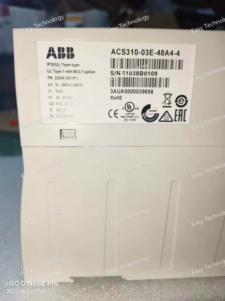
Key Specifications Parameter Category Specification Drive Series/Model ACS310-03E-48A4-4 Rated Output Current 48.4 A Rated Output Power 22 kW (30 HP) Input Supply Voltage 380 - 480 V AC (± 10%), 3-phase Input Supply Phases 3-phase Output Voltage 0 - Input voltage Output Phases 3-phase Enclosure Rating IP20 / UL Open Type (Chassis). Requires installation in a protective cabinet. Cooling Method Fan-cooled Control Methods • Scalar Control (V/f) • ABB Direct Torque Control (DTC) for superior dynamic performance. Key Standard Features • Intelligent Pump and Fan Control (IPF): Includes auto-tuning for energy optimization, multi-pump control logic, dry pump protection, and anti-jam functions. • Embedded Application Programming: Built-in function blocks (timers, logic gates, comparators) for creating custom control logic without an external PLC. • Adaptive Program (AUP): Guides user through commissioning based on selected application. • Built-in Communication Protocols: Modbus RTU (RS-485) and BACnet MS/TP are standard for building automation integration. • LCD Keypad: Clear display with multi-language support and parameter copy function. • Integrated EMC Filter (Class A). • PID Controller: Advanced controller with sleep/wake, cascade control, and PID freeze functions. Protection Features • Motor thermal overload protection (I²t) • Pump/Fan-specific protection (dry pump, overload, underload) • Short circuit, ground fault, overcurrent, overvoltage protection • IGBT overtemperature protection • Automatic fault reset and restart Application Focus Large HVAC systems (fans, pumps), pressure boosting, water supply, cooling towers, and industrial fluid handling applications.
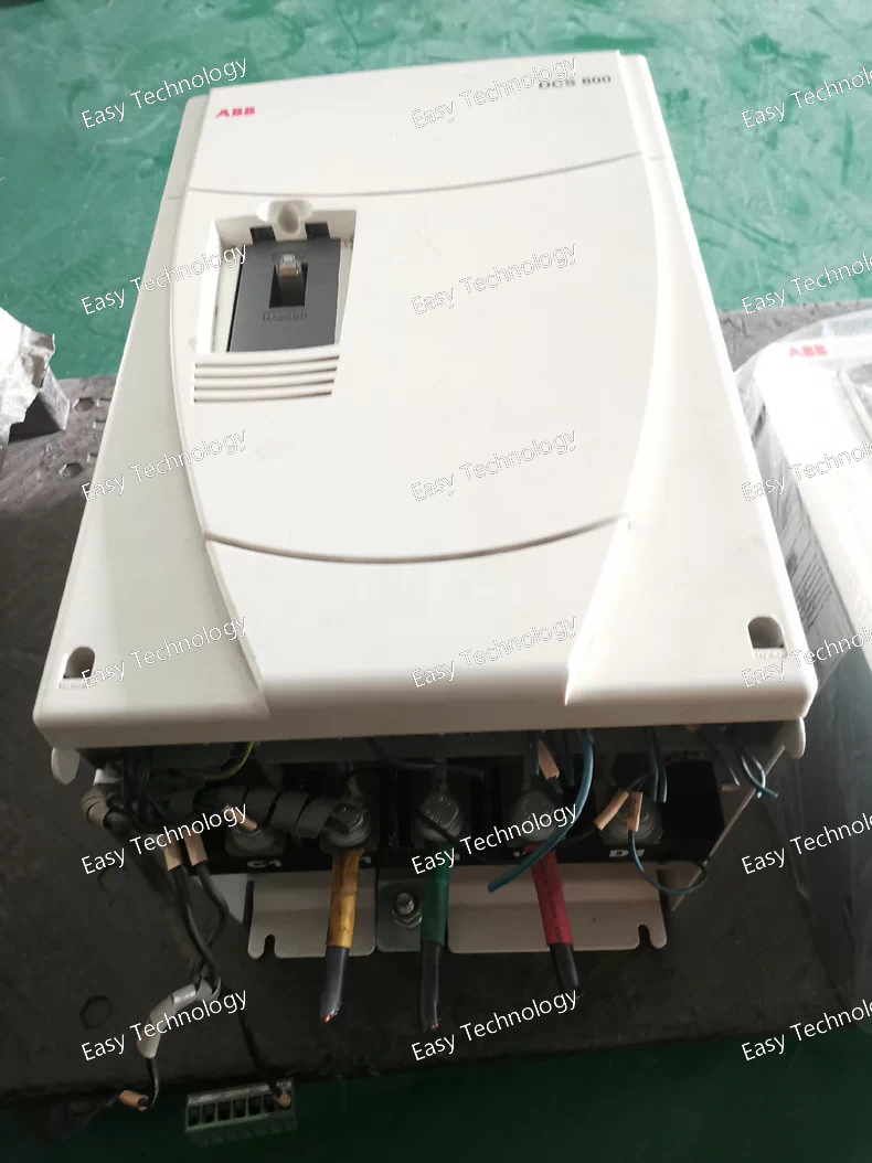
Key Specifications Parameter Category Specification Drive Series/Model DCS800-S02-0350-05 Motor Type DC Motor (Separate Armature & Field Supply) Rated Armature Current 350 A (Continuous DC Output) Rated Power Output ~160 kW (215 HP) (Estimated for a typical 460V DC motor armature). Power is voltage-dependent. Configuration Single Quadrant (S02): Forward motoring operation only. Cannot accept regenerative energy. Power Input 3-phase, 400V AC (±10%), 50/60 Hz (typical for "-05" code). Armature Output Voltage Variable DC, typically up to ~500V DC (for 400V AC supply). Field Supply Output Included. Adjustable DC output for motor field excitation. Control Method Digital thyristor (SCR) converter control. Programmable via DriveWindow™ software or control panel. Key Features • Digital Control Unit (DCU) for advanced programming. • Precise Speed Regulation (tachometer or EMF feedback). • Torque Control capability. • Extensive configurable I/O. • Field Weakening for extended speed range. • Comprehensive diagnostics and monitoring. Protection Features • Armature & field overcurrent. • Motor thermal overload (I²t). • Mains phase loss & undervoltage. • Overvoltage & overspeed. • Heatsink overtemperature. Typical Applications Large extruders, winders/unwinders (without regeneration), heavy mixers, machine tools, and large fans/pumps using DC motors.
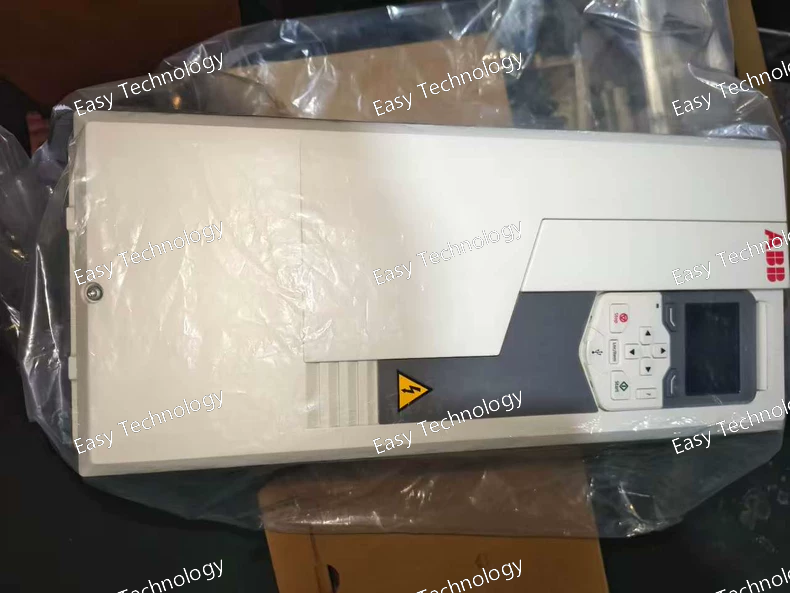
Key Specifications Parameter Category Specification Drive Series/Base Model ACS580-01-044A-4 Rated Output Current 44 A Rated Output Power 22 kW (30 HP) Input Supply Voltage 380 - 480 V AC (± 10%), 3-phase Output Voltage/Phases 3-phase, 0 - Input voltage Enclosure Rating IP21 / UL Type 1 Cooling Method Fan-cooled Control Method ABB Direct Torque Control (DTC) Key Standard Features • Energy Optimizer: Automatically minimizes energy losses. • Intelligent Control Panel (IOP): Multilingual graphical display. • Embedded Application Macros: For pumps, fans, etc. • Built-in Modbus RTU (RS-485). • Built-in EMC Filter (Class A). Option +K454 Integrated Safe Torque Off (STO) Safety Function • Function: Prevents unexpected motor start-up by safely disabling the inverter's power output. • Safety Level: SIL 3 according to IEC 61800-5-2 / PL e according to ISO 13849-1. • Implementation: Two independent, safety-certified input channels for connection to safety devices (e.g., safety relays, PLCs, emergency stops). Protection Features • Comprehensive motor thermal and electrical protection. • Integrated functional safety via +K454. Application Focus Conveyors, mixers, pumps, fans, and general machinery where integrated personnel safety is required for maintenance or access.
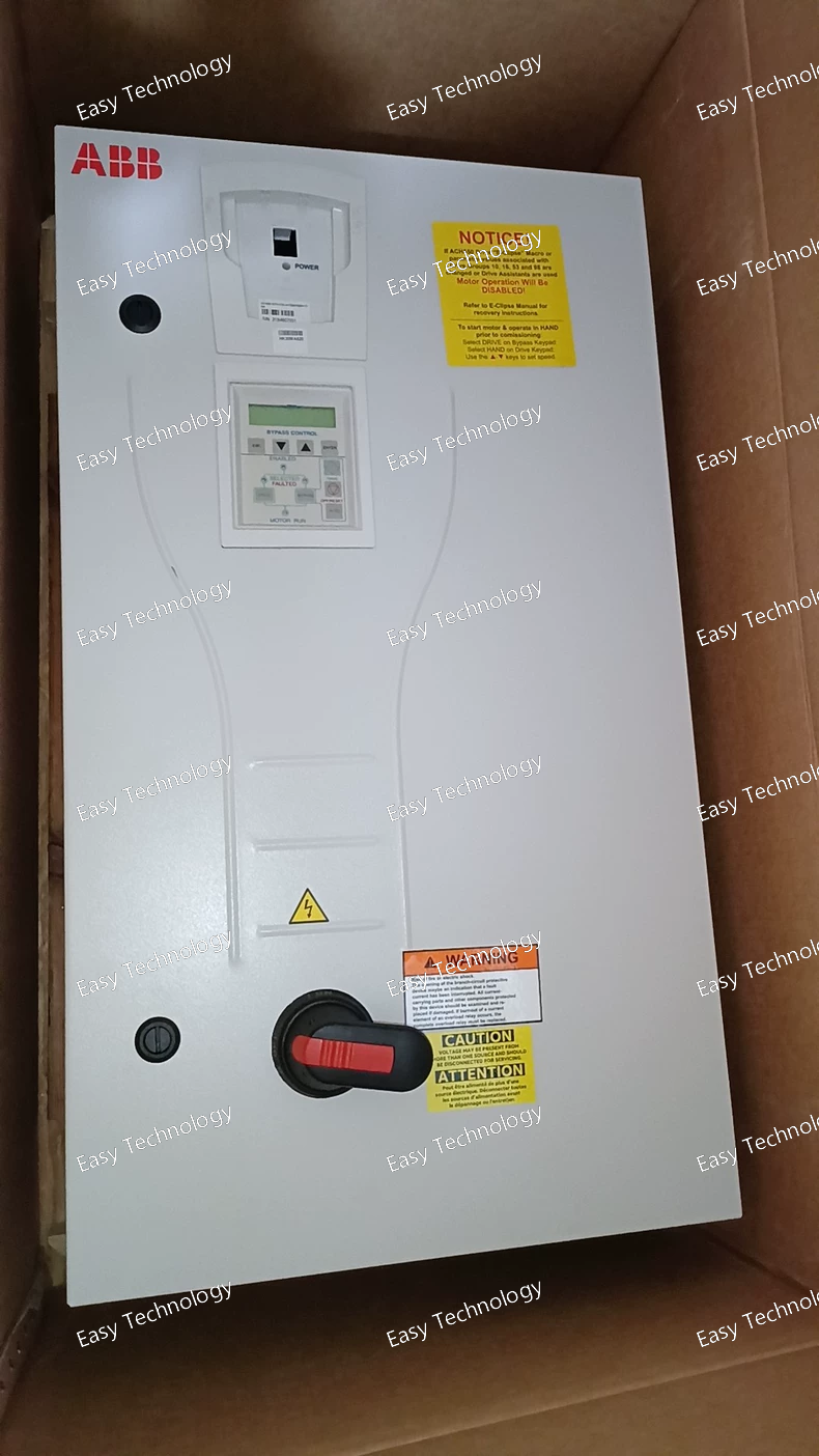
Key Specifications Parameter Category Specification Drive Series/Base Model ACH550-BCR-012A-4 (Bypass Controller Ready) Rated Output Current 12 A Rated Output Power 5.5 kW (7.5 HP) Input/Output Voltage 380 - 480 V AC, 3-phase Enclosure Rating Designed for mounting within a bypass starter panel (specific enclosure depends on the panel builder). Control Method ABB Sensorless Flux Control (MFC) for HVAC. Key BCR Features • Dedicated logic and terminals for interfacing with external bypass contactors. • Automatic/manual transfer control between drive and bypass modes. • Motor current monitoring in bypass mode (optional). Option +C558 Embedded EtherNet/IP Adapter • Protocol: EtherNet/IP™ (Scanner/Adapter). • Ports: 2 x RJ45. • Function: Enables direct network integration for control and monitoring from a BMS or PLC (e.g., Allen-Bradley). Option +N2006 Extended I/O Kit • Function: Expands the drive's native I/O capacity to handle the complex switching logic and status monitoring of a bypass system. Option +X1558R Relay Output Expansion Kit • Function: Adds crucial Form C (changeover) relay outputs necessary to physically command the bypass contactors and provide isolated status signals (e.g., "Drive Running," "Bypass Active," "Fault"). Protection Features • Standard drive and motor protection. • Bypass system interlocks to prevent shorts. Application Focus Critical HVAC Systems with Bypass Requirements: Chilled Water Pumps, Condenser Pumps, Cooling Tower Fans, Critical Air Handling Units.
 TEL: Grace +86 13600179521
  Mail: info@hongkongeasy.com jilineasyyi@outlook.com
 Q Q:615739355
 ADDRESS:Unit 12, 20th Floor, Good View Commercial Centre, 2-16 Garden Street, Mong Kok, Hong Kong
 whats app


