
Industrial Controller
All product are in stock,guaranteed delivery within 3-7 days.


PRODUCT
PICTURE
BRAND
DESCRIBE
STOCK
DOWNLOAD
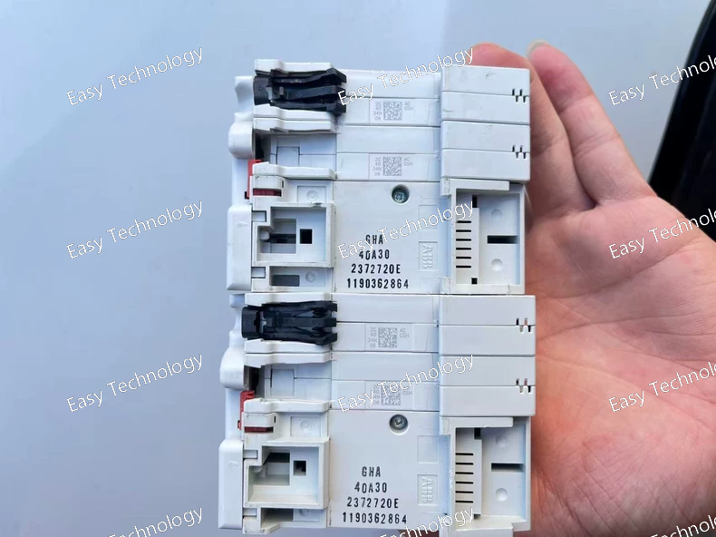
Technical Parameters Parameter Category Specification Details / Notes Product Series G-H Series High-Performance Contactors Device Type 3-Pole AC Power Contactor Standard Compliance IEC/EN 60947-4-1, IEC/EN 60947-1 Main Circuit Ratings • Rated Operational Voltage (Ue) Up to 690 V AC, 50/60 Hz • Rated Insulation Voltage (Ui) 1000 V AC • Rated Operational Current (Ie) 200 A (at AC-3, 400V) This is the key rating indicated by 202 (200A frame). Control Coil • Coil Type Available in AC and DC versions. Model suffix specifies: GSH202 AC or GSH202 DC. • Standard Coil Voltages (Us) AC: 24, 48, 110, 230, 400, 500V AC, 50/60 Hz. DC: 24, 48, 110, 220V DC. Must be specified when ordering. Utilization Categories • AC-3 Squirrel-cage motors: Starting, switching off during running. Rating: 200 A at 400V. Standard motor duty. • AC-4 Squirrel-cage motors: Starting, plugging, inching. Rating: ~75 A at 400V. Severe duty (reduced rating). • AC-1 Non-inductive or slightly inductive loads. Resistive loads. • AC-2 Slip-ring motors. Switching Capacity • Rated Making Capacity (Icm) Up to 2000 A (peak) at 415V AC, cos φ=0.35. For handling motor inrush. • Rated Breaking Capacity Icu (Ultimate): Typically 15-20 kA at 415V AC. Ics (Service): A high percentage of Icu. Short-circuit withstand (with backup protection). Endurance • Mechanical Life ≥ 10 million operations (minimum). • Electrical Life (AC-3) 1.0 - 2.0 million operations at full rated load (200A, 400V). Power Consumption • Pick-up (Inrush) ~1800 VA (for AC coil). Momentary during closing. • Holding (Sealed) ~30 VA (for AC coil, energy-efficient). Auxiliary Contacts Modular blocks available. Typical: 2 NO + 2 NC per block. Rated: 10A, 600V AC. Can be added on sides. Terminals Screw-clamp terminals for large cables (e.g., up to 185 mm²). May support busbar connections. Mounting Foot mounting or snap-on DIN Rail adapter (optional). Ambient Temperature Operating: -25°C to +60°C (up to +70°C with derating). Storage: -50°C to +80°C. Protection Degree IP00 (open type). With cover: IP20. Must be installed in an enclosure. Dimensions (approx.) ~ 185 mm (L) x 150 mm (W) x 140 mm (H) (base unit). Varies with accessories. Weight (approx.) ~ 5.5 kg (base unit). Key Features • High electrical & mechanical endurance • Modular & expandable design • Energy-saving magnet system • Transient suppression (AC coils) • Contact position indicator • Manual operator
Technical Parameters Parameter Category Specification Product Series / Family ABB G-H Series High-Performance Contactors Device Type 3-Pole AC Power Contactor (Definite Purpose) Standard Compliance IEC/EN 60947-4-1, IEC/EN 60947-1 Rated Operational Voltage (Ue) Up to 690 V AC, 50/60 Hz Rated Insulation Voltage (Ui) 1000 V AC Rated Operational Current (Ie) at AC-3 200 A (This is the key rating indicated by 202 in the model number: 200A frame). Note: Actual continuous current depends on thermal conditions, load category, and duty cycle. Control Coil Voltage (Us) Various AC Voltages (e.g., 24V, 48V, 110V, 230V, 400V, 500V AC, 50/60 Hz). The AC in the model name specifies an AC-operated coil. DC coil versions are GSH202 DC. Utilization Categories • AC-3 Squirrel-cage motor: Starting, switching off during running. Typical rating: 200 A at 400V. • AC-4 Squirrel-cage motor: Starting, plugging, inching. (Rating is significantly lower, e.g., ~75 A). • AC-1 Non-inductive or slightly inductive loads. • AC-2 Slip-ring motors. Rated Making/Breaking Capacity • Making Capacity (Icm) Up to 2000 A (peak, at 415V AC, cos φ=0.35) for high inrush currents. • Breaking Capacity (Icu/Ics) Icu (Ultimate): Typically 15-20 kA at 415V AC. Ics (Service): Typically a percentage of Icu (e.g., 75%). Mechanical & Electrical Life • Mechanical Durability 10 - 20 million operations (minimum, depends on conditions). • Electrical Durability (AC-3) 1.0 - 2.0 million operations at full rated load (200A, 400V). Power Consumption • Pick-up (Inrush) Power ~1800 VA (typical for AC coil). • Holding (Sealed) Power ~30 VA (typical, energy-efficient design). Auxiliary Contacts Modular add-on blocks available, typically 2 NO + 2 NC per block, up to several blocks. Rated: 10A, 600V AC. Terminals Screw-clamp terminals suitable for large cross-section cables (e.g., up to 185 mm²). Some versions may have busbar connections. Mounting Mounts on a flat surface or panel via foot mounts or snap-on DIN rail adapter (optional). Ambient Temperature Operating: -25°C to +60°C (up to +70°C with derating). Storage: -50°C to +80°C. Protection Degree IP00 (open type, must be installed in an enclosure for protection). With cover: IP20. Approximate Dimensions (L x W x H) ~ 185 mm x 150 mm x 140 mm (varies with auxiliary blocks). Approximate Weight ~ 5.5 kg (base unit). Key Features • Modular and expandable design. • High electrical and mechanical endurance. • Energy-saving AC magnet system. • Transient suppression (RC network) for AC coils. • Front-mounted, visible contact position indicator. • Manual operator for testing and maintenance.
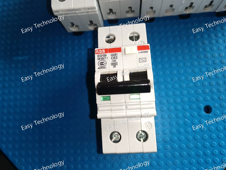
Technical Parameters Parameter Category Specification Product Series System Pro M - GS Rotary Switch-Disconnector Device Type Manual Rotary Switch-Disconnector (Isolator) Standard Compliance IEC/EN 60947-3, IEC/EN 60947-1 Rated Operational Voltage (Ue) 690 V AC Rated Insulation Voltage (Ui) 800 V AC Rated Impulse Withstand Voltage (Uimp) 8 kV Rated Frequency 50/60 Hz Rated Current (Ith / Ie) Up to 125 A (Depending on the specific model/pole version and enclosure). Common frame sizes: 32A, 63A, 125A. Utilization Category AC-23A (For switching of squirrel-cage motors with inrush currents up to 8 x Ie). Also suitable for AC-20, AC-21, AC-22. Short-Circuit Performance • Rated Conditional Short-Circuit Current (Icq) Typically 10 kA (When backed by appropriate upstream fuses, e.g., gG/gL type). • Rated Making Capacity (Icm) Up to 12.5 kA (peak, depends on version). Mechanical & Electrical Life • Mechanical Durability ≥ 20,000 operations. • Electrical Durability ≥ 5,000 operations at full rated load (AC-23A). Number of Poles Available in: 1-pole (1P), 2-pole (2P), 3-pole (3P), and 4-pole (4P) versions. Switching Position Clearly marked ON (I) and OFF (O) positions. Padlockable in the OFF position with up to 3 padlocks (standard) for safety lockout/tagout (LOTO). Connection & Terminals Screw-clamp terminals suitable for both copper and aluminum cables (with appropriate treatment). Mounting Can be mounted on a standard 35 mm DIN Rail (EN 60715) or directly on a panel. Actuation Rotary handle operation. Handle can be mounted on the device (direct) or remotely via an extension kit. Enclosure Material High-strength, self-extinguishing thermoplastic (Polyamide PA 6.6). Protection Rating (with enclosure) Up to IP65 (when properly installed with enclosure and gasket), providing protection against dust and water jets. Front panel typically IP40. Ambient Temperature Operating: -25°C to +70°C Storage: -50°C to +85°C Common Optional Accessories • Auxiliary Contacts (for signaling ON/OFF status). • Fuse Holders (to create a switch-fuse combination, e.g., with NH or CC gG/gL fuses). • Extension Shafts for remote operation. • Cable Glands and Enclosures. Safety Approvals CE, cULus, CCC, and other international standards.
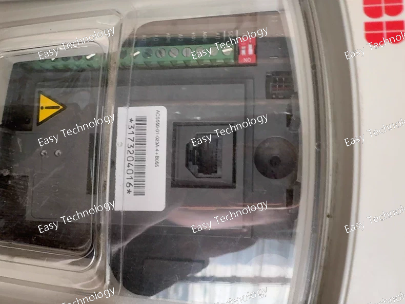
Technical Parameters Parameter Category Specification Notes Series / Family ACS550 - General Purpose Drive Part of the ABB Industrial Drives family. Product Type Variable Frequency Drive (VFD) / Adjustable Speed Drive (ASD) For controlling 3-phase AC induction motors. Supply Voltage 3-phase, 200...240 V AC ±10% Defined by -01- in the code. Frequency: 48...63 Hz. Output Power 4.0 kW (5.5 hp) Defined by 023A: 023 corresponds to a frame size, A indicates 4.0kW at 240V. Output Current 12.0 A (Continuous) Maximum continuous output current. Motor Control Mode Volts/Hertz (Scalar Control) with optional Flux Optimization (MTC). Provides energy-efficient scalar control. Enclosure Rating IP21 / NEMA Type 1 (Open chassis) For mounting inside a control cabinet. -4 indicates a chassis unit without an operator panel. Key Features - Built-in PID Controllers (2) for process control. - 7 Custom Macros for quick application setup. - Follow-up (Flying Start). - Energy Savings mode via Flux Optimization. - Modbus RTU communication (RS485) as standard. - Safe Torque Off (STO) safety function (SIL 2). Focus on pump, fan, and compressor control. Option Code (+B055) Internal Braking Chopper + Braking Resistor Kit +B indicates an internal brake chopper is present. 055 specifies a matching braking resistor kit (e.g., a specific ohmic value and power rating) for dynamic braking. Control Connections - 2 Analog Inputs (0/4...20 mA or 0...10 V) - 2 Analog Outputs (0/4...20 mA) - 6 Digital Inputs (24 V DC) - 2 Digital/Relay Outputs - RS485 port Standard I/O for basic control and monitoring. Protection Features Motor overload, short circuit, ground fault, overvoltage, undervoltage, overtemperature, phase loss, etc. Comprehensive drive and motor protection. Ambient Temperature -10°C to +40°C (up to +50°C with derating) Requires adequate ventilation. Storage Temperature -40°C to +70°C Relative Humidity < 95% (non-condensing) Altitude < 1000 m above sea level without derating. Requires current derating at higher altitudes. Mounting Wall-mounted inside a cabinet. Approx. Dimensions (W x H x D) ~ 150 mm x 245 mm x 187 mm Dimensions vary slightly by frame size. Approx. Weight ~ 3.5 kg
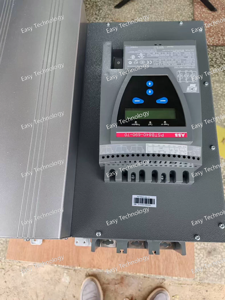
Technical Parameters Parameter Category Specification Product Series / Platform ABB Relion® 670 Series (Bay Control & Protection) Device Type Numerical Bay Control and Protection Unit Key Standards IEC 60255, IEC 61850 (Edition 2), IEC 60870-5-103/-104 Rated Auxiliary Supply (Us) 48 - 250 V DC / 48 - 240 V AC, 50/60 Hz (Suffix -70). Other ranges (-11, -12) available. Analog Inputs • Current (CT) Inputs Up to 6 current inputs, configurable for 1 A or 5 A secondary. 690 in code often indicates a specific I/O configuration. • Voltage (VT) Inputs Up to 6 voltage inputs, typically 100/110 V or 100/√3 V line-to-neutral. Protection Functions (Comprehensive Suite) Includes but is not limited to: • Differential Protection (87B, 87T) • Distance Protection (21) with multiple zones • Directional/Nondirectional Overcurrent (67/50, 51) • Breaker Failure Protection (50BF) • Over/Under Voltage & Frequency (27/59, 81) • Synchrocheck (25) • Arc Protection (optional) Control & Interlocking • Bay Control Full local/remote control of circuit breakers, disconnectors, earthing switches. • Programmable Logic Powerful CLP (Configuration Logic Programming) for custom interlocking, automation sequences, and signal processing. • Binary I/O Extensive configurable binary inputs and outputs (e.g., 48 BI, 40 BO). Measurement & Metering High-accuracy measurement of I, V, P, Q, S, PF, f, energy, harmonics, etc. Class 0.5 per IEC 61869. Human-Machine Interface (HMI) • Display Large, high-resolution color graphical LCD with intuitive menu structure. • Interface Front USB port for configuration and data extraction. Keypad for local operation. Data Recording • Event Recorder ≥ 5000 time-tagged events with sequence-of-events (SOE) resolution. • Disturbance Recorder High-speed fault recording (oscillography) with analog channels and binary signals. • Maintenance Data Breaker operation statistics, load profile, thermal overload history. Communication Interfaces Multiple, redundant ports: • Front: Ethernet (RJ45), USB. • Rear: 2-4 Ethernet ports (RJ45 or fiber) for station bus (IEC 61850-8-1, GOOSE). Serial ports (RS485) for legacy protocols (IEC 60870-5-103, Modbus). Time Synchronization Supports IRIG-B, SNTP/NTP, and PTP (IEEE 1588). Environmental • Operating Temperature -25°C to +70°C (Extended range: -40°C to +70°C optional) • Protection Rating IP54 (front panel) for harsh substation environments. Mechanical & Mounting 19-inch rack mountable (4U height) or panel-mounted version available. Robust metal housing. Configuration Software PCM600 – ABB's universal engineering tool for parameter setting, logic configuration, and documentation. Typical Applications HV/MV feeder protection & control, transformer protection (high-side), busbar protection, capacitor bank protection.
Technical Parameters Parameter Category Specification Product Family / Type Self-Powered Three-Phase Current Monitoring Relay Protection Functions • Phase Loss Detection • Phase Sequence (Rotation) Monitoring • Current Asymmetry (Unbalance) Protection Standard Compliance IEC/EN 60947-5-1 Power Supply Self-powered from the secondary side of the connected current transformers (CTs). Rated Input Current (In) 1 A AC (Secondary current of the CTs, defined by -600-). Operating Current Range 0.1 A to 1.3 A AC per phase. System Frequency 50 / 60 Hz. Protection Settings • Threshold Current (I<) Adjustable via rotary switch. Sets the minimum current level for phase presence detection. Typical range: 0.15 x In to 0.95 x In. • Asymmetry Trip Level Adjustable via rotary switch. Sets the permissible current imbalance between phases as a percentage. Typical range: 20% to 70% asymmetry. • Phase Sequence Fixed for one direction (e.g., L1-L2-L3). Trip on reversal is instantaneous. • Response Time Fixed internal delay (typically < 0.5s) to avoid nuisance tripping on transient conditions. Output Contact • Type 1 Changeover (CO) contact (SPDT: 1 NO + 1 NC). • Rated Operational Current (Ie) 6 A at 250 V AC (Utilization category AC-15). Binary Input • Reset / Start Input (A1, A2) 1 input. Requires a 24-48 V DC pulse (defined by suffix -11) to close the output relay after a fault condition is cleared or upon initial energization. Visual Indication 2 LEDs: - GREEN (On): Power OK, correct phase sequence, all phase currents above threshold. - RED (Trip): Fault detected (Phase Loss, Sequence Error, or Asymmetry). Connection Terminals Screw-clamp terminals for: - 3 Current Inputs (From 1A secondary CTs, must be connected in Star/Wye). - Output Contact (13-14 NO, 21-22 NC). - Reset Input (A1, A2). Electrical Isolation Reinforced insulation between current circuits, output contact, and reset input. Operating Temperature -25°C to +55°C Storage Temperature -40°C to +85°C Mounting Standard 35mm DIN Rail (EN 60715). Housing & Protection Self-extinguishing thermoplastic (PA 6.6), IP40 (front), IP20 (terminals). Dimensions (W x H x D) Approx. 22.5 mm x 100 mm x 112 mm (1 module width = 22.5mm). Weight Approx. 0.15 kg. Certifications CE, cULus, RoHS.
Technical Parameters Parameter Category Specification Product Family / Type Self-Powered 3-Phase Voltage Monitor with Motor Start Feature Monitoring Functions 1. Phase Sequence (Rotation) Control 2. Phase Loss / Undervoltage Detection 3. Voltage Asymmetry (Unbalance) Monitoring 4. Voltage Dip Ride-Through during Motor Start Standard Compliance IEC/EN 60947-5-1 Power Supply Self-powered from the monitored 3-phase line voltage (L1, L2, L3). Rated Operational Voltage (Ue) 3 x 208...480 V AC, 50/60 Hz (Phase-to-Phase). Current Input (for Start Logic) 1 A AC nominal (via external Current Transformers - CTs). Parameter Settings & Ranges • Running Voltage Threshold (U<) Adjustable via potentiometer. Sets the minimum permissible voltage during normal operation. • Start Voltage Threshold Fixed internally or linked to Running Threshold. A less sensitive level active only during motor start. • Voltage Asymmetry (ΔU) Adjustable via potentiometer. Sets the maximum allowed voltage difference between phases. • Start Time Fixed internal timer defining the duration of the start monitoring mode (typically a few seconds). Output Contact • Type 1 Changeover (CO) contact (SPDT). • Rated Operational Current (Ie) 6 A at 250 V AC (AC-15 category). Binary Input • Reset / Start Input 1 input (Terminals A1, A2). Requires a 24-48 V DC pulse (suffix -11) to close the output contact after a fault or initial power-up. Visual Indication 2 LEDs: - GREEN (On): Supply healthy, correct sequence, parameters within limits. - RED (Trip): Fault condition (Loss, Unbalance, or Sequence Error). Electrical Connections Screw-clamp terminals for: - 3 Phase Voltages (L1, L2, L3). - 3 Current Inputs (From 1A secondary CTs, star-connected). - Output Contact (13-14 NO, 21-22 NC). - Reset Input (A1, A2). Isolation Reinforced insulation between all circuits: mains voltage, CT inputs, output contact, reset input. Operating Temperature -25°C to +55°C Storage Temperature -40°C to +85°C Mounting Standard 35mm DIN Rail. Housing & Protection Thermoplastic housing, IP40 (front), IP20 (terminal area). Dimensions (W x H x D) Approx. 45 mm x 100 mm x 112 mm (2 module width). Weight Approx. 0.2 kg. Certifications CE, cULus, RoHS.
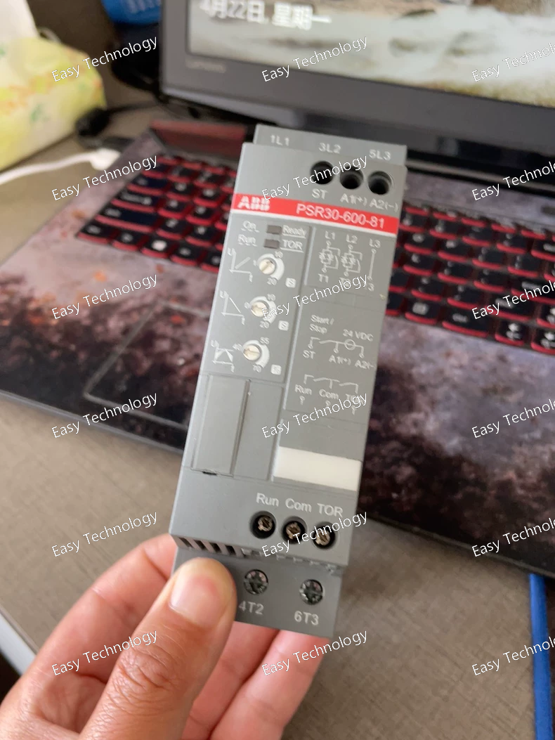
Technical Parameters Parameter Category Specification Product Family / Type Self-Powered 3-Phase Voltage Monitor with Motor Start Logic Key Functions 1. Phase Sequence (Rotation) Monitoring 2. Phase Loss (Undervoltage) Detection 3. Voltage Asymmetry (Unbalance) Monitoring 4. Motor Start Supervision (Temporary adaptation of thresholds during start) Standard Compliance IEC/EN 60947-5-1 Power Supply Self-powered from the monitored three-phase line voltage (L1, L2, L3). Rated Operational Voltage (Ue) 3 x 208...480 V AC, 50/60 Hz (Phase-to-Phase). Rated Current Input (In) 1 A AC (For motor start current measurement via external Current Transformers - CTs). Monitoring Parameters & Settings • Voltage Threshold (U<) Adjustable potentiometer. Sets the general minimum voltage level for normal running. • Asymmetry (Unbalance) Threshold Adjustable potentiometer. Sets the maximum permitted voltage imbalance between phases. • Start Mode Logic When motor current is detected (via CTs), the relay automatically switches to a less sensitive "Start Voltage Threshold" for a predefined time, allowing for the expected voltage dip during start-up. • Response Time (Running) Fixed time delay to avoid transients. Output Contact • Type 1 Changeover (CO) contact (SPDT: 13-14 NO, 21-22 NC). • Rated Load 6 A at 250 V AC (AC-15). Binary Inputs • Reset/Start Input (A1/A2) 1 input. A control voltage pulse (24-240V AC/DC, as indicated by suffix -81) must be applied to close the output relay after a fault or initial energization. Indications 2 LEDs: - GREEN (On): Supply healthy, correct sequence, all parameters OK. - RED (Trip): Fault condition (Loss, Unbalance, or Sequence Error). Connection Terminals Screw-clamp terminals for: - 3 Phase Voltages (L1, L2, L3). - 3 Current Inputs (From 1A CTs, connected in Star). - Output Contact (13, 14, 21/22). - Reset Input (A1, A2). Isolation Reinforced insulation between voltage circuits, current circuits, output contact, and reset input. Operating Temperature -25°C to +55°C Storage Temperature -40°C to +85°C Mounting 35mm DIN Rail (EN 60715). Housing & Protection Thermoplastic housing, IP40 (front), IP20 (terminals). Dimensions (W x H x D) Approx. 45 mm x 100 mm x 112 mm (2 module width = 45mm). Note: Width may vary slightly with exact model version. Weight Approx. 0.2 kg.
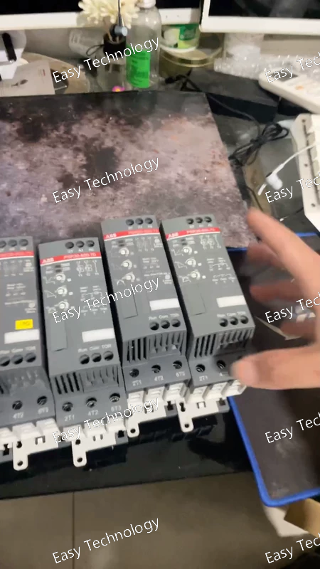
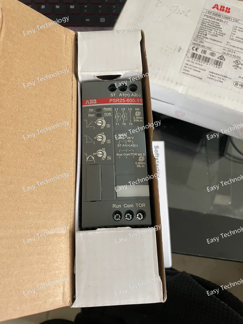
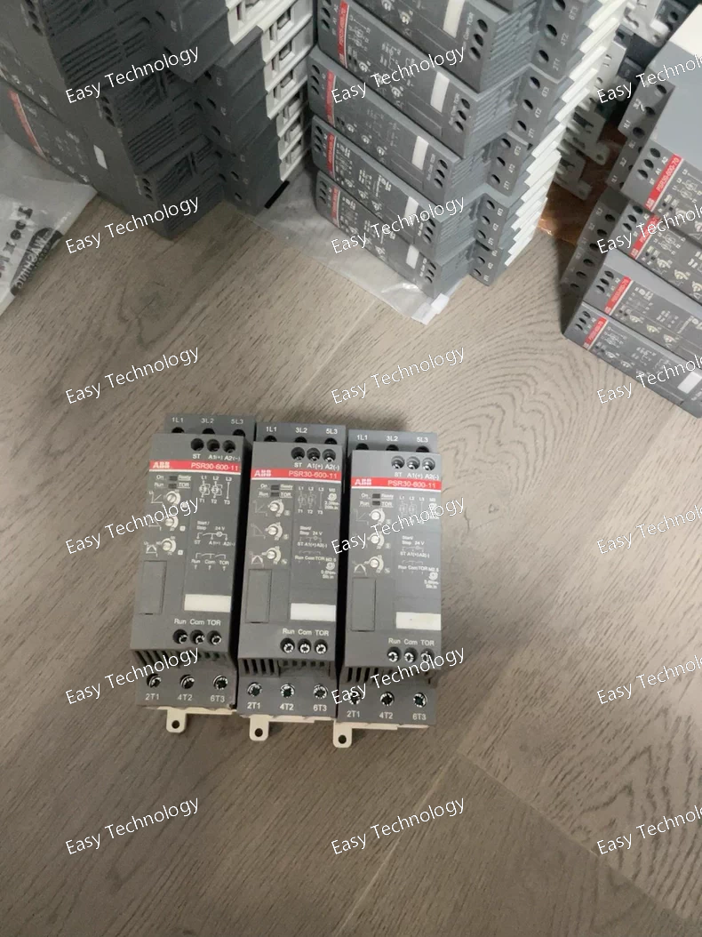
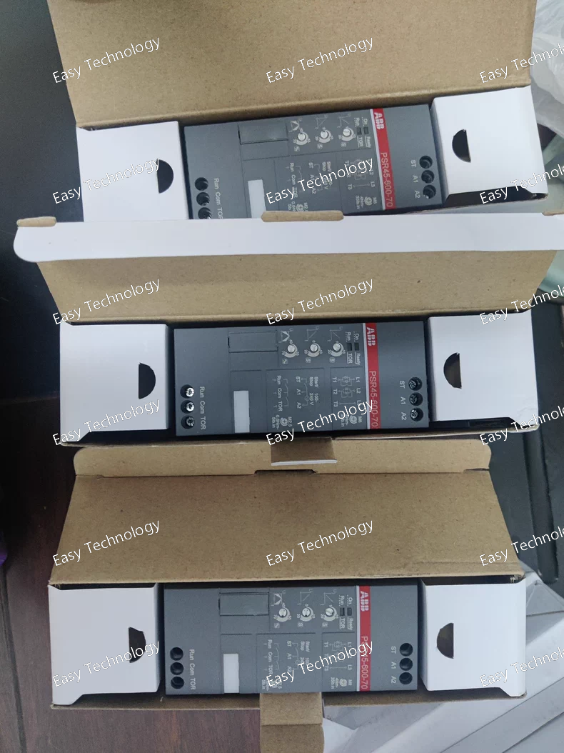
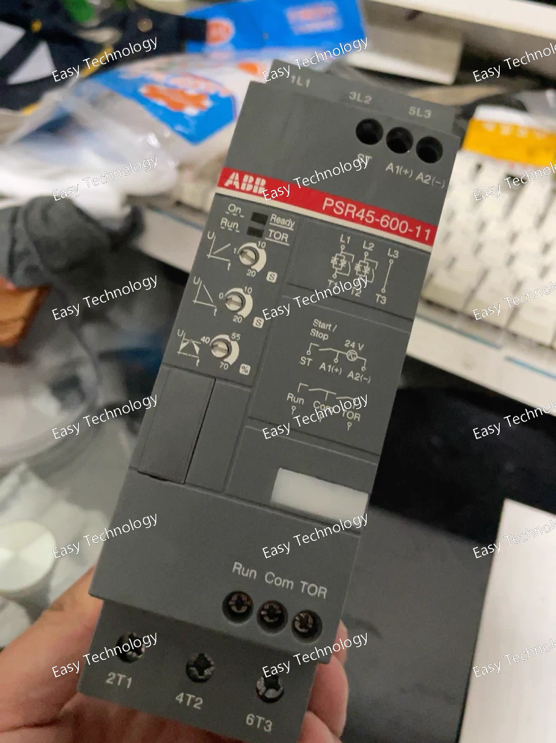
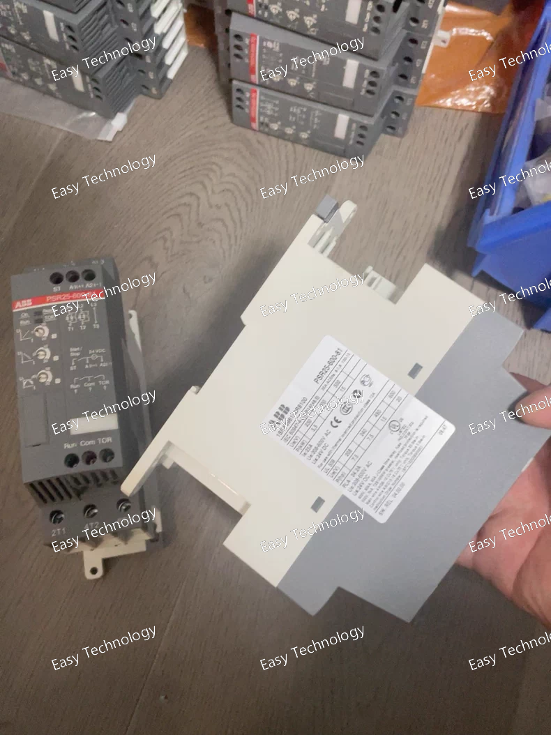
Technical Parameters Parameter Category Specification Product Family / Type Self-Powered Three-Phase Voltage Monitoring Relay Key Monitoring Functions • Correct Phase Sequence (Phase Rotation) • Phase Loss (Undervoltage per Phase) • Voltage Asymmetry (Unbalance) Standard Compliance IEC/EN 60947-5-1 Power Supply Self-powered from the monitored three-phase voltage system. No external auxiliary supply required. Rated Operational Voltage (Ue) 3 x 208...480 V AC, phase-to-phase. (50/60 Hz). The -70 suffix in this context indicates this wide voltage range. Operating Voltage Range 0.7 to 1.1 x Ue. Rated Current Input (In) 1 A AC (This is defined by the -600- in the type code and is related to an optional current-based function for voltage dip monitoring during motor start). Monitoring Parameters & Settings • Voltage Threshold (U<) Adjustable via rotary switch. Typically sets the minimum voltage level for phase loss detection. • Asymmetry Setting Adjustable via rotary switch. Sets the permissible voltage unbalance level between phases (e.g., as a percentage). • Response Time Fixed delay to prevent nuisance tripping from transient events. • Phase Sequence Fixed for one rotation (e.g., L1-L2-L3). Trips immediately on reversal. Output Contact • Type 1 Changeover (CO) contact (SPDT: 1 NO + 1 NC). • Rated Operational Current (Ie) 6 A at 250 V AC (AC-15). Binary Input 1 Reset/Start Input (Terminals A1/A2). A control voltage (matching the -70 range: 48-250V DC/AC) must be applied to close the output relay after a fault or upon initial power-up. Indications 2 LEDs: - Green (On) : Supply OK, correct sequence, all parameters within limits. - Red (Trip) : Fault condition detected (Phase Loss, Sequence Error, or Asymmetry). Connection Screw-clamp terminals for: - 3 Phase Voltage Inputs (L1, L2, L3, N optional). - Output Contact (13, 14, 23). - Reset Input (A1, A2). - Optional Current Inputs (for PSR30 models with motor start function). Electrical Durability ≥ 100,000 mechanical operations. Isolation Reinforced insulation between voltage circuits, output contact, and reset input. Operating Temperature -25°C to +55°C Storage Temperature -40°C to +85°C Mounting Standard 35mm DIN Rail. Housing Material Self-extinguishing thermoplastic (Polyamide PA 6.6). Protection Rating IP40 (front), IP20 (terminals). Dimensions (W x H x D) Approx. 22.5 mm x 100 mm x 112 mm (1 Module width = 22.5mm). Weight Approx. 0.15 kg. Certifications CE, cULus, RoHS.
Technical Parameters Parameter Category Specification Product Family / Type Compact, Configurable Multifunction Protection Relay Standard Compliance IEC 60255, IEC 60947-1, -5-1 Rated Auxiliary Supply (Us) 48 - 250 V DC / 48 - 240 V AC, 50/60 Hz (Auto-ranging, defined by suffix -70) Rated Current Input (In) 1 A AC (Defined by -600-. -500- indicates 5 A). Configurable Functions (via DIP Switch) Selectable as one of: 1. 3-phase overcurrent (I>) 2. 2-phase overcurrent (I>) 3. 1-phase overcurrent (I>) 4. Sensitive earth-fault (I0>) 5. 3-phase OC + Earth-fault (I> + I0>) Protection Characteristics • Operate Value (Pick-up) Phase: 0.2 x In to 1.0 x In (10 steps via DIP) Earth: 0.02 x In to 0.2 x In (10 steps via DIP) • Time Delay Definite Time (DT) only. Adjustable via potentiometer: 0.06 s to 3.0 s. • Reset Time ~60 ms (Instantaneous). • Reset Ratio > 95% of operate value. • Operate Time Tolerance ±5% of set value or ±30 ms. Output Contacts • Trip Relay (K1) 1 Changeover (CO) contact (SPDT). Rating: 8 A at 250 V AC (AC-15) / 5 A at 30 V DC (DC-13). • Signal Relay (K2) 1 Changeover (CO) contact (SPDT). Configurable for trip replication or as an independent pre-alarm. Binary Input 1 programmable input for Remote Reset or Blocking function. Indications 3 LEDs: • GREEN (PWR): Supply healthy. • YELLOW (ALARM): Pre-alarm / Start signal active. • RED (TRIP): Protection operated. Burden & Consumption < 0.2 VA per current circuit at In. Typical power: < 3 W. Isolation 2.5 kV RMS (50 Hz, 1 min) between all circuits: supply, current inputs, outputs. Environmental • Operating Temperature -25°C to +55°C • Storage Temperature -40°C to +85°C • Relative Humidity ≤ 93% (non-condensing) Mechanical • Mounting Standard 35 mm DIN Rail (EN 60715). • Housing Material Self-extinguishing thermoplastic (Polyamide PA 6.6), UL94 V-0. • Protection Rating IP40 (front), IP20 (terminals). • Dimensions (W x H x D) 70 mm x 122 mm x 116 mm (4 module width). • Weight ~0.45 kg. Certifications CE, cULus, RoHS, EAC.
Parameter Category Specification Product Family / Type Compact Configurable Multifunction Protection Relay Standard Compliance IEC 60255, IEC 60947-1 Rated Auxiliary Supply Voltage (Us) 24 - 48 V DC (This is defined by the -11 suffix). Rated Current Input (In) 1 A AC (This is defined by the -600- in the type code. 600 = 1A; 500 = 5A). Configurable Functions (via DIP Switch) The relay can be configured as one of the following: 1. Three-phase overcurrent relay (I>) 2. Two-phase overcurrent relay (I>) 3. Single-phase overcurrent relay (I>) 4. Sensitive earth-fault relay (I0>) 5. Three-phase overcurrent + Earth-fault relay (I> + I0>) Protection Characteristics & Settings • Operate Value (Pick-up) Phase Fault: Adjustable from 0.2 x In to 1.0 x In via a 10-position DIP switch. Earth Fault: Adjustable from 0.02 x In to 0.2 x In via a 10-position DIP switch. • Time Delay Definite Time (DT). Adjustable via a front potentiometer: 0.06 seconds to 3.0 seconds. • Reset Time Instantaneous (approx. 60 ms). • Reset Ratio > 95% of the operate value. Output Contacts • Trip Relay (K1) 1 Changeover (CO) contact (SPDT). • Rated Load: 8 A, 250 V AC / 5 A, 30 V DC. • Signal Relay (K2) 1 Changeover (CO) contact (SPDT). • Can be configured for Trip Replication or as an independent Pre-alarm. Binary Input 1 programmable input. Can be assigned as a Remote Reset or Blocking input. Indications 3 LEDs: - GREEN (PWR): Power ON. - YELLOW (ALARM): Pre-alarm or start signal activation. - RED (TRIP): Protection has operated (trip condition). Burden < 0.2 VA per current circuit at In. Typical power consumption: < 3 W. Isolation 2.5 kV RMS between all circuits (supply, current inputs, output contacts). Operating Temperature -25°C to +55°C Storage Temperature -40°C to +85°C Mounting Standard 35mm DIN Rail (EN 60715). Housing Material Self-extinguishing thermoplastic (Polyamide PA 6.6), UL94 V-0 rated. Protection Rating IP40 (front), IP20 (terminal area). Dimensions (W x H x D) Approx. 70 mm x 122 mm x 116 mm (4 module width = 70mm). Weight Approx. 0.45 kg. Certifications CE, cULus, RoHS.
Parameter Category Specification Product Family / Type Numerical Motor Protection Relay (Electronic Overload Relay) Standard Compliance IEC/EN 60255, IEC/EN 60947-4-1, -8 Rated Auxiliary Supply Voltage (Us) 48 - 250 V DC / 48 - 240 V AC, 50/60 Hz (Auto-ranging, suffix -70) Rated Motor Current Setting (Iu) 0.1 A - 1000 A (Wide setting range, independent of hardware). The -600- in the code typically indicates the factory default or compatible CT secondary rating of 1A. Current Sensor Input Accepts signals from standard 1 A or 5 A secondary Current Transformers (CTs) or Rogowski Coils. Core Protection Functions • Thermal Overload (49) Digital thermal replica model with separate heating (during run/start) and cooling constants. Adjustable Iu (Full Load Current), Trip Class (5…40), and Ambient Temperature compensation. • Phase Unbalance / Loss (46) Protection based on negative-sequence current calculation. • Short-Circuit / Instantaneous OC (50) High-set, instantaneous trip for short-circuit protection. • Earth Fault (50N/51N) Residual current protection (via Core Balance CT or calculated). Can be set as instantaneous or time-delayed. • Locked Rotor / Stall (48/14) Separate stall protection with adjustable stall time. • Start-up Supervision Monitors start time and protects against prolonged starts. • Number of Starts / Restart Inhibit Programmable limits to prevent motor overheating from frequent starts. Configuration & Interface • Front Panel Controls Rotary Switches for setting Iu, Isd (Short Circuit), t6x (Stall Time). DIP Switches for enabling functions (Earth Fault, Unbalance), selecting CT ratio, and setting Ie (Earth Fault current). • PC Software (Optional) ABB PSRsoft for advanced configuration, real-time monitoring, and data logging via the front USB port. Output Contacts • Trip Relay (CO) 1 Changeover contact (95-96 NO, 97-98 NC). • Alarm Relay 1 (CO) 1 Changeover contact, typically pre-assigned to Thermal Pre-alarm (e.g., at 90% thermal capacity). • Alarm Relay 2 (CO) 1 Changeover contact, programmable for other alarms (e.g., Unbalance, Earth Fault, General Alarm). • Binary Inputs 2 programmable inputs for functions like External Reset, General Alarm Input, or Underload Enable. Monitoring & Indication • Measured Values Phase currents (L1, L2, L3), maximum current, earth-fault current, thermal capacity used (%), motor status. • LED Indicators 7 LEDs: PWR (Green), TRIP (Red), ALARM (Yellow), START, RUN, COMM, G.ALARM. • Fault Memory Stores the last fault type (Overload, Unbalance, Stall, Earth Fault, etc.). Communication (Optional) Can be equipped with a plug-in communication module for: Modbus RTU (RS485), Profibus DP, or DeviceNet. Motor Thermal Memory Includes a supercapacitor to retain the thermal memory and clock for several hours in case of auxiliary power loss. Operating Temperature -20°C to +60°C Storage Temperature -40°C to +85°C Mounting Standard 35mm DIN Rail (EN 60715). Housing & Protection Plastic housing, IP20 protection degree. Dimensions (W x H x D) Approx. 70 mm x 125 mm x 121 mm (4 module width = 70mm).
 TEL: Grace +86 13600179521
  Mail: info@hongkongeasy.com jilineasyyi@outlook.com
 Q Q:615739355
 ADDRESS:Unit 12, 20th Floor, Good View Commercial Centre, 2-16 Garden Street, Mong Kok, Hong Kong
 whats app


