
Industrial Controller
All product are in stock,guaranteed delivery within 3-7 days.


PRODUCT
PICTURE
BRAND
DESCRIBE
STOCK
DOWNLOAD
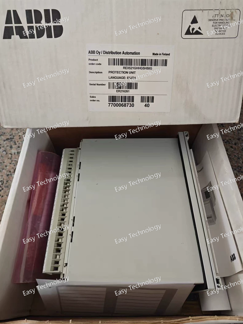
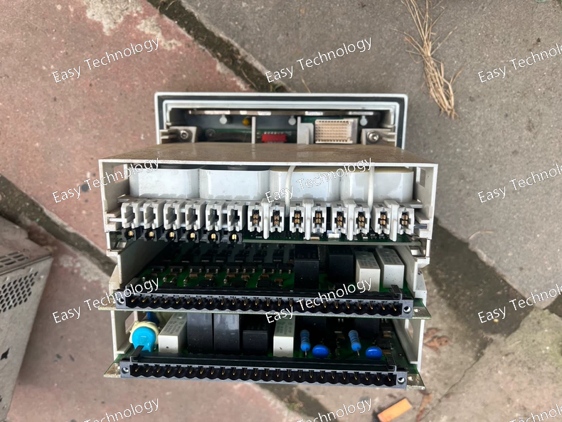
Parameter Category Specification Device Platform ABB Relion® 650 Series, REX521 Feeder Protection Relay Standard Compliance IEC 60255, IEC 61850 (Ed.2), IEEE C37.90 Rated Auxiliary Supply 48 - 250 V DC (Wide Range) Protection Functions Configurable via software. Standard library includes: • Directional/Non-directional Overcurrent (50/51, 67) • Directional/Non-directional Earth Fault (50N/51N, 67N) • Over/Under Voltage (27/59) • Over/Under Frequency (81) • Breaker Failure (50BF) • Thermal Overload (49) Analog Inputs • Current: At least 4 channels (3-phase + earth), 5A nominal. • Voltage: 3-phase voltage inputs (typically 100/110V line-to-line or phase-to-neutral) are standard. Binary Inputs (BI) Minimum 16 channels, 24-48V DC. Binary Outputs (BO/Relays) Minimum 8 channels, Form-C contacts. Communication Interfaces • Ethernet: At least 1 port (RJ45 or fiber) for IEC 61850, IEC 60870-5-104. • Serial: At least 1 RS485 port for Modbus RTU or IEC 60870-5-103. • Front Port: USB for local configuration. Human-Machine Interface Graphical LCD with keypad. LED indicators. Measurement & Metering High-accuracy measurement of I, V, P, Q, S, PF, f, kWh, kVARh. Class 0.5. Event & Disturbance Recording Event recorder (≥ 1000 events). Fault recorder (oscillography) capability. Configuration Software ABB PCM600 – Universal engineering tool for setting, logic configuration, and documentation. Typical Mounting Panel-mounted (4U height, 19-inch rack) or DIN rail mounting variant possible.
Technical Parameters Parameter Category Specification Compatible Breaker Series ABB Emax 2 (E2) Air Circuit Breakers (Fixed & Draw-out versions). Rated Frame Current (In) Matches the breaker frame size. Common frames: E2.1 (1600A), E2.2 (2000A), E2.3 (3200A), E2.4 (4000A), E2.5 (5000A), E2.6 (6300A). The PR122/P is scaled for these ranges. Power Supply Self-powered from the current sensors of the breaker. No external auxiliary power required for basic protection functions. Core Protection Functions (LSI) • Long-time Protection (L) Adjustable Settings: - Ir (Rated Current): 0.4 to 1.0 x In (in steps). - tr (Time Delay): Adjustable, typically following an I²t inverse-time curve. • Short-time Protection (S) Adjustable Settings: - Isd (Short-time Current): 1.5 to 15 x Ir (in steps). - tsd (Short-time Delay): Adjustable in seconds (e.g., 0.05 to 0.5s) or as I²t curve. Can be set to OFF for selectivity. • Instantaneous Protection (I) Adjustable Settings: - Ii (Instantaneous Current): 1.5 to 15 x In, or fixed high value (e.g., 20kA). Can be set to OFF. Ground-Fault Protection (Optional) Available as an add-on module (PR122/P + G). The base LSI version does not include ground-fault protection. Measurement & Display • Display Backlit LCD graphical display on the trip unit. • Measured Values Real-time display of: Phase currents (L1, L2, L3), Neutral current (if sensor present), Ground current, Max current, Power (kW, kVA), Power Factor, Frequency, Energy (kWh), etc. • Metering Accuracy Class 1 per IEC 61557-12. Communication Standard: RS485 port with Modbus RTU protocol. Event Logging Stores time-stamped records of trips, alarms, and breaker operations (Open, Close). Configuration Via front keypad or via ABB Emax Connect PC software through the communication port. Testing Built-in trip test function to verify the health of the trip unit and the breaker's operating mechanism. Ambient Temperature -25°C to +70°C (Operating) Standards IEC 60947-2, UL 489, CSA C22.2 Key Feature Selectivity (Coordination): The adjustable S and I delays allow for precise time-current coordination with downstream breakers, minimizing outage impact during a fault.
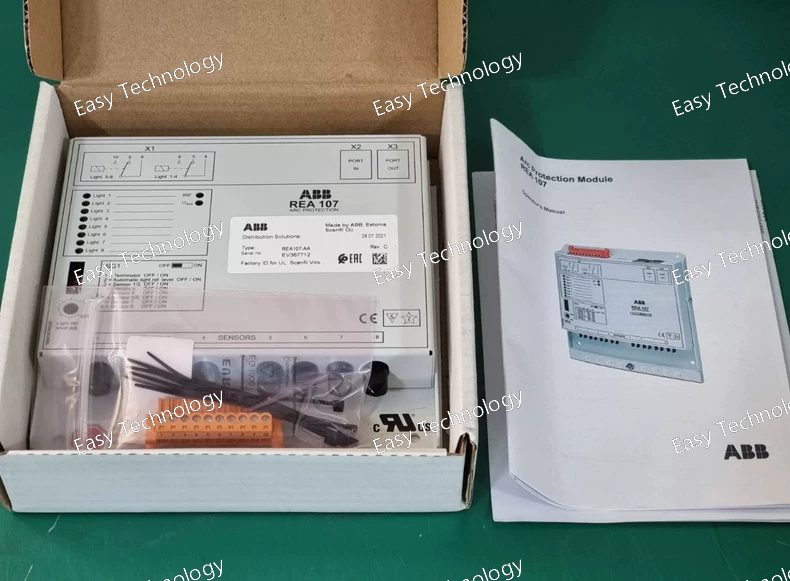
Technical Parameters Parameter Category Specification / Interpretation Type Window-Type (Bushing-Type), Single-Turn Primary, Cast Resin Insulated Current Transformer Standard IEC 61869-1 & IEC 61869-2 (formerly IEC 60044-1) Rated Primary Current (Ipn) Likely 100A, 150A, 200A, 300A, or 400A. The exact value is defined by the full model. "107" might indicate a 100A base. Rated Secondary Current (Isn) 1 A or 5 A (Most common secondary ratings). Accuracy Class -AA Suffix Interpretation: • The first 'A' very likely stands for the protection core's accuracy class (e.g., 5P or 10P). • The second 'A' often indicates the metering core's accuracy class (e.g., 0.5 or 1.0). Thus, REA 107-AA is highly probable to be a Dual-Core CT with one core for protection and one for measurement. Rated Output (VA) Protection Core: Typically 10 VA or 15 VA at specified accuracy class (e.g., 10P10). Metering Core: Typically 5 VA or 10 VA at specified accuracy class (e.g., 0.5). Accuracy Limit Factor (ALF) For Protection Core (if 5P or 10P): Typically 10 or 15 (e.g., 10P10 means 10% composite error at 10 times rated current). Rated Dynamic Current (Idyn) Typically 2.5 x Ith (Rated short-time thermal current). Rated Short-Time Thermal Current (Ith) Expressed in kA for 1s or 3s. For a CT of this size, could be in the range of 10 - 25 kA for 1s. Rated Insulation Level (kV) Likely 12/24/36 kV (Rated voltage / Power-frequency withstand / Lightning impulse withstand). Common for 7.2kV or 12kV systems. Example: 12/28/75 kV. Window Diameter / Size Determines the maximum size of the primary conductor (busbar) that can pass through. A common size is Ø50mm or 50x100mm (rectangular). Mounting Designed for fixed installation on a panel structure, often with mounting feet or brackets. Ambient Temperature Operating: -5°C to +40°C (up to +55°C with derating) Weight Approx. 3 - 7 kg, depending on size.
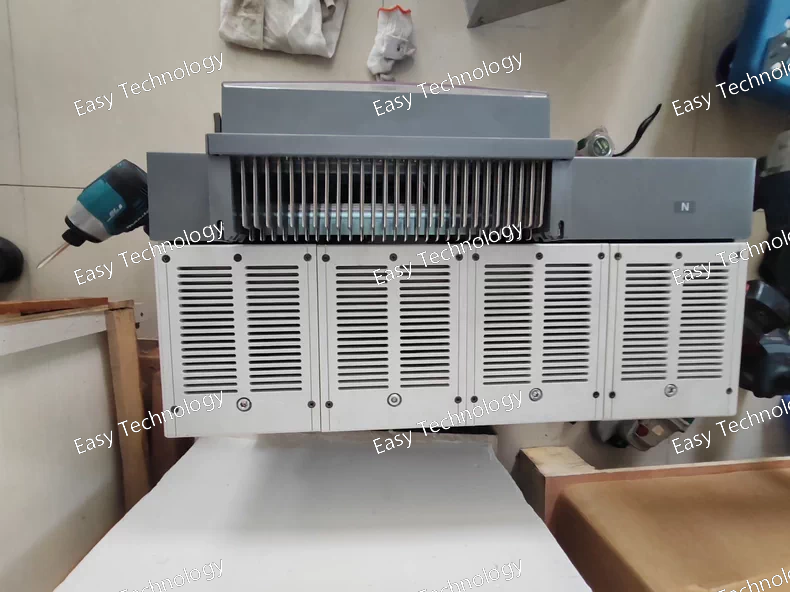
Technical Parameters Parameter Category Typical Specification for this Configuration General • Rated Voltage (Ur) 12 kV • Rated Frequency 50 / 60 Hz • Insulation Level 12/32 kV (Power freq./Impulse) • Design Standard IEC 62271-100, ANSI C37.06 Current Ratings • Rated Normal Current (Ir) 1500 A • Rated Short-Circuit Breaking Current (Isc) 25 kA or 31.5 kA (Must verify with drawing 54617997) • Rated Short-Time Withstand Current (Ik) Typically equals Isc for 3s. • Rated Peak Withstand Current (Ip) Typically 2.5 x Isc. Switching Performance • Rated Breaking Capacity Full Isc at Ur. • Mechanical Endurance ≥ 20,000 operations (M2 class) • Electrical Endurance ≥ 10,000 operations at full Ir (E2 class) Operating Mechanism (F) • Type Spring-operated, stored energy. • Charging Motor Electric motor, voltage per drawing 54617997. • Closing Time ~60 – 80 ms • Opening Time ~40 – 60 ms Releases (G included) • Standard Protections Integrated with external protection relay. The breaker has shunt trips and auxiliary switches to interface with it. • Undervoltage Release (G) Trips the breaker upon loss of control power. Voltage per drawing. • Other Possible Releases Overcurrent releases, special locking coils (not indicated in this code). Vacuum Interrupter • Type Axial magnetic field or radial field, for long contact life. • Rated Switching Currents Suitable for transformer, cable, and motor switching. Dimensions & Weight • Width Approx. 600 – 800 mm (depends on panel design) • Weight Approx. 150 – 200 kg
Technical Parameters Parameter Specification System / Standard KNX / EN 50090, ISO/IEC 14543 Bus Voltage 21 – 32 V DC (KNX SELV) Auxiliary Supply (Us) 24 V DC, SELV (±10%) Power Consumption • From KNX Bus: Typically < 10 mA • From Aux. Supply: Depends on relay state; ~20 mA per active relay + quiescent. Channels 2 Binary Inputs + 2 Relay Outputs (Typical interpretation of DACADAN) Binary Inputs • Type: Dry contact (potential-free) or voltage monitor (24V DC). • Function: Configurable as switch, push-button, counter, etc. via ETS software. Relay Outputs • Contact Type: 1 changeover (SPDT) per channel. (NO + NC + COM) • Rated Load (AC-1): 16 A / 250 V AC • Motor Load (AC-3): 10 A / 250 V AC (for squirrel-cage motors) • Inrush Current (Ic): 150 A (for a limited number of cycles). Electrical Life ≥ 100,000 operations at rated load (AC-1) Mechanical Life ≥ 1,000,000 operations Status Indication LED per channel (configurable) + LED for bus & power status. Local Manual Control Yes, via integrated pushbuttons (indicated by suffix E). Mounting 35 mm DIN Rail (EN 60715) Ambient Temperature Operating: -5°C to +45°C Storage: -25°C to +55°C Protection Degree IP20 (for mounting in a distribution board) Configuration Exclusively via ABB ETS (Engineering Tool Software) using a unique device database file. Dimensions (WxHxD) Approx. 8 modules (144 mm) x 90 mm x 65 mm
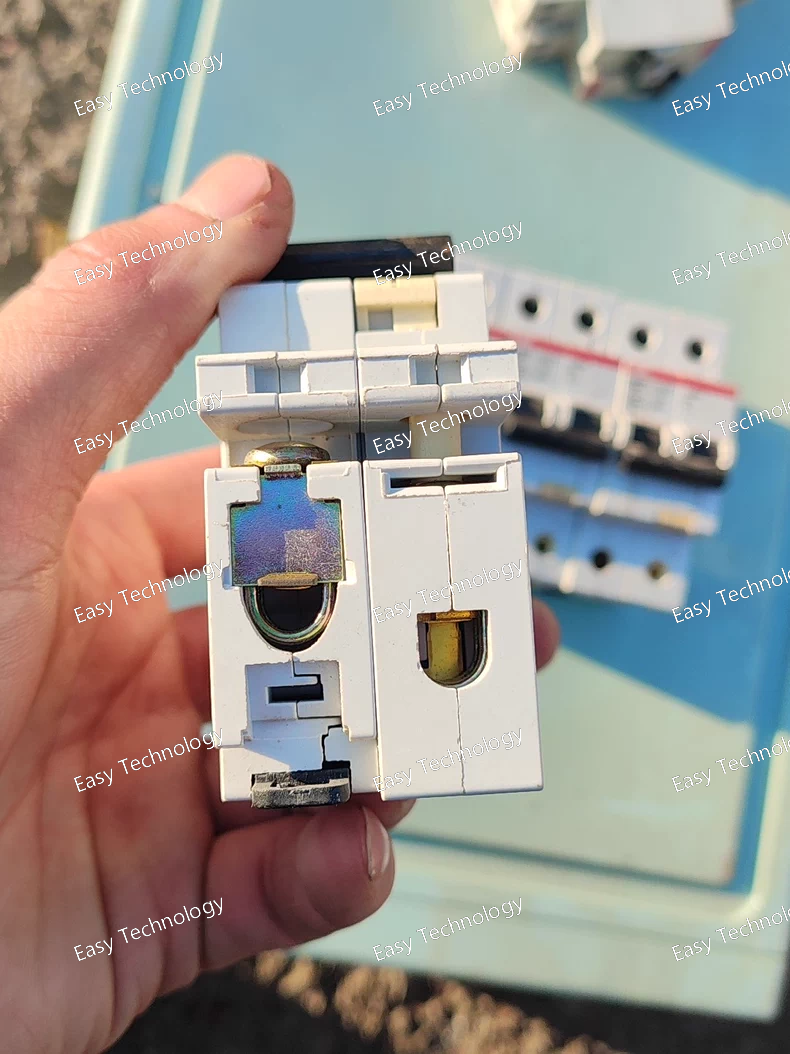
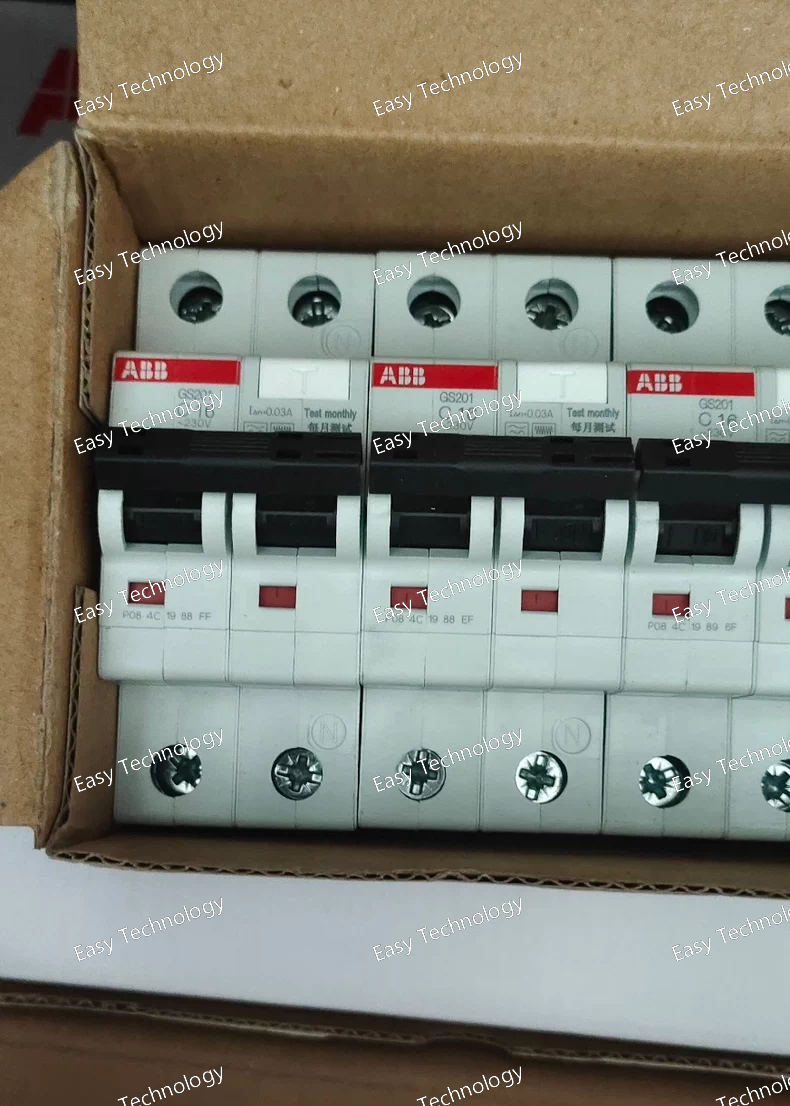
Parameter Specification Notes / Explanation Series / Type System Pro M - GS Rotary Switch-Disconnector (Special Version) Device Type 3-Pole Load Break Switch-Disconnector with Integrated Low-Current Fuse Standard Compliance IEC/EN 60947-3, IEC/EN 60947-1 Poles 3 Poles (Main Circuit) Main Circuit Ratings • Rated Operational Voltage (Ue) 690 V AC • Rated Insulation Voltage (Ui) 800 V AC • Rated Operational Current (Ie) 63 A (AC-23A) The 251 in GS251S indicates the 63A frame size. Breaking Capacity • Rated Conditional Short-Circuit Current (Icq) Typically 10-15 kA (when backed by specified upstream fuses) Requires backup fuse. Handle (C16) • Type Front-mounted, rotary handle with a large black knob. For manual operation and padlocking. • Locking Can be padlocked in the OFF position (usually 1-2 padlocks). Essential for LOTO. Special Feature (/0.03) Key Feature • Description Integrated low-current fuse holder or protection link for an auxiliary circuit. • Rated Current 0.03 A (30 mA) gG or similar characteristic. • Protected Circuit Type Likely a set of dedicated low-current auxiliary contacts or a separate isolated terminal pair for control/signaling. Purpose is to protect sensitive external control devices. • Physical Form Could be a 5x20mm or similar miniature fuse housed within the switch body or handle assembly. Utilization Category AC-23A (For switching squirrel-cage motors) Mechanical Life ≥ 20,000 operations Electrical Life (AC-23A) ≥ 5,000 operations at full rated current Auxiliary Contacts The S version and /0.03 likely imply the presence of special auxiliary contacts with the low-current fuse in series with one of them. Standard auxiliary blocks may also be addable. Terminals Screw-clamp terminals. Main terminals accept larger cables. Connection Capacity Up to 35 mm² (for main terminals) Mounting Mounts on 35 mm DIN Rail (EN 60715). Protection Degree IP40 (with handle installed) Ambient Temperature Operating: -25°C to +70°C Dimensions (W x H x D) Approx. 80 mm x 135 mm x 120 mm (for 3-pole unit) Weight Approx. 0.7 kg (without fuses)
Technical Parameters Parameter Specification Notes / Explanation Series / Type System Pro M - GS Switch-Disconnector with Fuse Bases Device Type 3-Pole Load Break Switch-Disconnector with Fuse Bases Standard Compliance IEC/EN 60947-3, IEC/EN 60947-1 Poles 3 Poles (Main Circuit) + Fuse Poles Main Circuit Ratings • Rated Operational Voltage (Ue) 690 V AC • Rated Insulation Voltage (Ui) 800 V AC • Rated Operational Current (Ie) 32 A (AC-23A) Switch mechanism rating. Fuse Specification (F) Key Feature • Fuse Type D-type (Cylindrical) Fuses per IEC 60269, e.g., 10x38mm or 14x51mm sizes. This is indicated by the F in the model code (vs. NH for knife-blade fuses). • Fuse Rating Range Typically accepts fuses from 0.5A to 32A (gG/gL) or up to 63A (aM). Actual max depends on the specific fuse base version. • Short-Circuit Performance Rated Conditional Short-Circuit Current (Icq) is typically 50 kA when used with specified D-type fuses. Handle (C16) • Type Front-mounted, rotary handle with a large black knob. Mounts directly on the front of the switch body. • Function Manual operation, clear ON/OFF indication. Can be padlocked in the OFF position (usually 1-2 padlocks). Utilization Category AC-23A (For switching of squirrel-cage motors) Also suitable for AC-20, AC-21, AC-22. Mechanical Life ≥ 20,000 operations Electrical Life (AC-23A) ≥ 5,000 operations at full rated current Auxiliary Contacts Optional add-on auxiliary contact blocks (e.g., GS-AX series) for signaling. Not included in base F C16 version. Terminals Screw-clamp terminals. Connection Capacity Up to 16 mm² (for main terminals) Mounting Mounts on 35 mm DIN Rail (EN 60715). Protection Degree IP40 (with handle installed) Ambient Temperature Operating: -25°C to +70°C Pollution Degree PD 3 Dimensions (W x H x D) Approx. 72 mm x 122 mm x 115 mm (for 3-pole switch-fuse) Weight Approx. 0.6 kg (without fuses) Safety Approvals CE, cULus, CCC, etc.
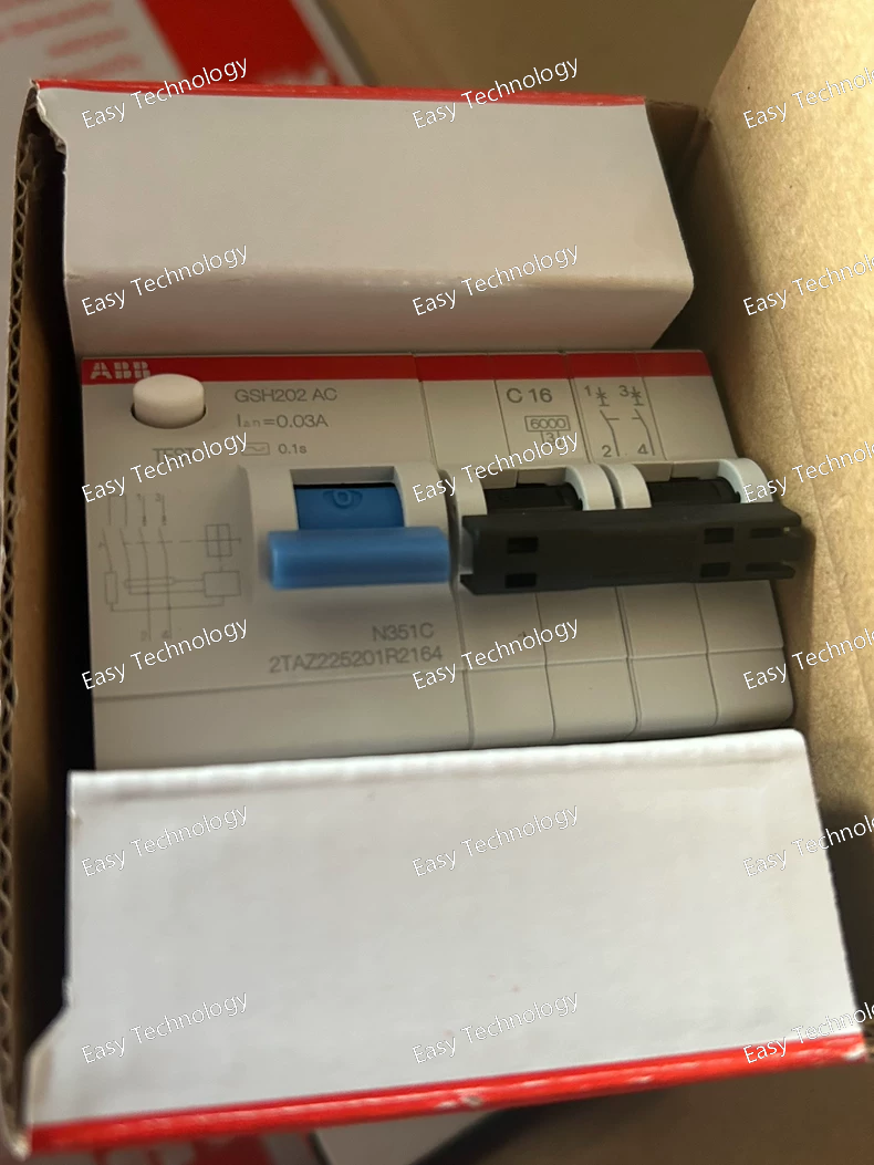
Parameter Category Specification Base Device GSH202 AC 200A Main Circuit Ratings • Rated Operational Current (Ie) 200 A (at AC-3, 400V) • Rated Operational Voltage (Ue) Up to 690 V AC Handle / Actuator -C16 Critical Special Specification /0.03 Control Coil Fuse (/0.03) • Protected Circuit The contactor's AC control coil circuit (terminals A1, A2). • Fuse Rating 0.03 A (30 mA) gG or similar characteristic. • Purpose To protect the control transformer, PLC output, or control switch from damage in case of an internal coil fault or short circuit in the control wiring. Utilization Categories AC-3, AC-4, AC-1 Switching Capacity Icm: ~2000A; Icu: 15-20 kA Endurance Mechanical: ≥10M ops; Electrical (AC-3): 1-2M ops Auxiliary Contacts Modular blocks available (e.g., 2NO+2NC) Mounting Foot mounting or DIN rail adapter Ambient Temperature -25°C to +60°C
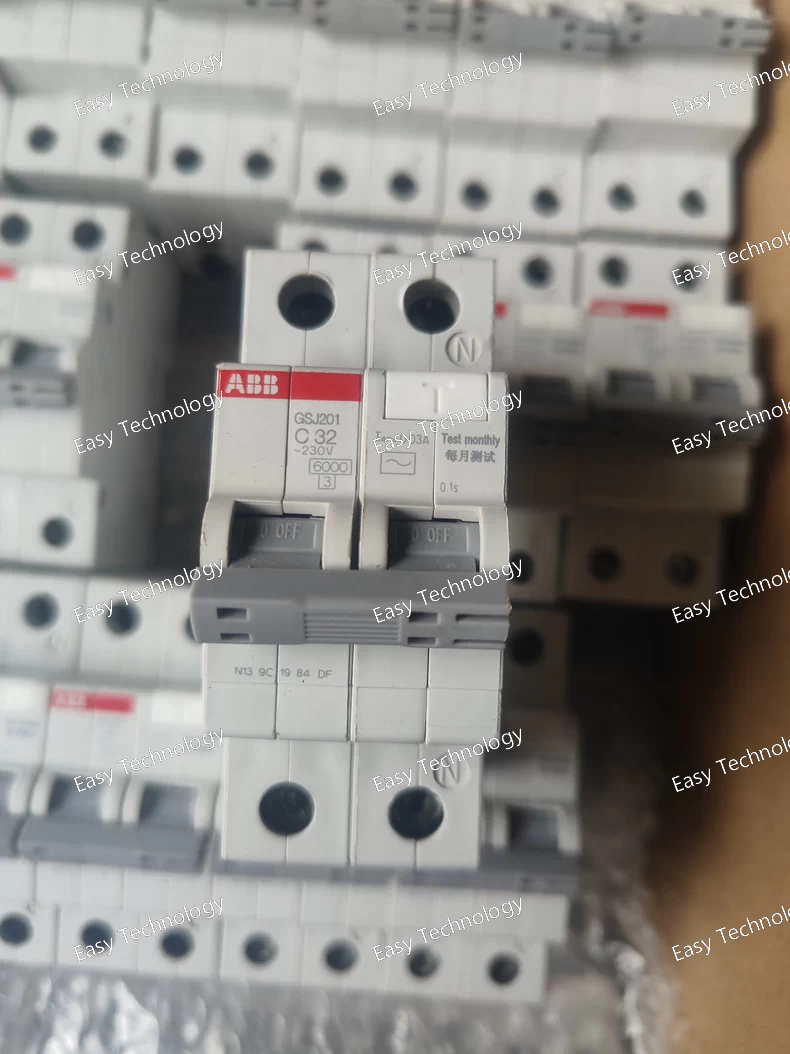
Technical Parameters Parameter Specification Notes / Explanation Series / Type System Pro M - GSJ High Breaking Capacity Switch-Disconnector Device Type Manual Rotary Switch-Disconnector (Isolator) Provides visible isolation gap. Standards IEC/EN 60947-3, IEC/EN 60947-1 Poles 3 Poles (Standard for this frame). Also available in 2-pole and 4-pole versions with different codes. Main Circuit Ratings • Rated Operational Voltage (Ue) 690 V AC • Rated Insulation Voltage (Ui) 800 V AC • Rated Impulse Withstand Voltage (Uimp) 8 kV • Rated Operational Current (Ie) 32 A (at AC-23A) The 201 in GSJ201 typically indicates the 32A frame size. Breaking Capacity Key differentiator of the GSJ series. • Rated Service Short-Circuit Breaking Capacity (Ics) 25 kA at 415V AC, cos φ=0.25 Can interrupt a 25kA fault and remain operational. • Rated Ultimate Short-Circuit Breaking Capacity (Icu) 36 kA at 415V AC, cos φ=0.25 Maximum fault current it can safely interrupt. • Rated Making Capacity (Icm) 66 kA (peak) at 415V AC For closing against short-circuit. Utilization Category AC-23A (For switching of squirrel-cage motors, up to 8xIe inrush) Also suitable for AC-20, AC-21, AC-22. Mechanical Life ≥ 20,000 operations Electrical Life (AC-23A) ≥ 5,000 operations at full rated current Handle (C32) Key Feature • Type Flush-mounted, square-shaped rotary handle. Provides a flat, professional panel appearance. • Knob Black rotary knob, can be padlocked in the OFF position (typically up to 3 padlocks). • Mounting Installed through a 30x30 mm square cutout in the panel door. • Position Indicator Clear ON (I) / OFF (O) marking on the knob. Auxiliary Contacts Optional add-on auxiliary contact blocks (e.g., GS-AX series) for signaling ON/OFF status. Not included in base C32 version. Terminals Screw-clamp terminals suitable for copper/aluminum cables. Connection Capacity Up to 35 mm² (for main terminals) Mounting Mounts on 35 mm DIN Rail (EN 60715) or directly on a panel. The switch body is mounted inside the cabinet. Protection Degree IP40 (with handle installed on a panel) Ambient Temperature Operating: -25°C to +70°C Pollution Degree PD 3 For industrial environments. Dimensions (Switch Body) Approx. 75 mm (W) x 120 mm (H) x 110 mm (D) Weight Approx. 0.5 kg (switch body only) Safety Approvals CE, cULus, CCC, etc.
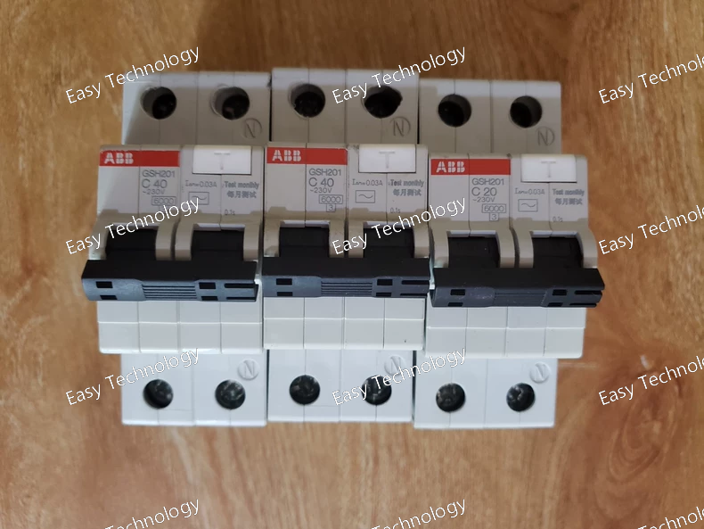
Technical Parameters Parameter Specification Notes / Explanation Series / Type G-H Series High-Performance Contactor Device Type 3-Pole AC Power Contactor with Manual Operator Standards IEC/EN 60947-4-1, IEC/EN 60947-1 Main Circuit Ratings • Rated Operational Voltage (Ue) Up to 690 V AC, 50/60 Hz • Rated Insulation Voltage (Ui) 1000 V AC • Rated Operational Current (Ie) 100 A (at AC-3, 400V) The 201 indicates the 100A frame size. Control Coil Must be specified separately. C40 refers to the handle, NOT the coil voltage. • Coil Voltage (Us) Various AC & DC voltages available (e.g., 24V AC/DC, 110V AC, 230V AC, 400V AC). Ordered as a separate code (e.g., GSH201 A230 for 230V AC coil + C40 handle). Utilization Categories • AC-3 Squirrel-cage motors: Starting, switching off. Rating: 100 A at 400V. Standard duty. • AC-4 Squirrel-cage motors: Starting, plugging, inching. Rating: ~40-50 A at 400V. Severe duty (derated). • AC-1 Non-inductive loads. Switching Capacity • Rated Making Capacity (Icm) ~1000 - 1200 A (peak) For motor inrush. • Rated Breaking Capacity (Icu) Typically 10-15 kA at 415V AC Requires backup fuse/circuit breaker. Endurance • Mechanical Life ≥ 10 million operations • Electrical Life (AC-3) ≥ 1.0 million operations at 100A, 400V Manual Operator (C40) Key Feature • Type Side-mounted, rotary handle. • Function Manual opening/closing of main contacts for testing, maintenance, or emergency stop. • Locking Handle can be padlocked in the OFF position (typically with 1-3 padlocks) for safety lockout/tagout (LOTO). • Position Indicator Clear ON/OFF indication. Power Consumption (Coil) Example for 230V AC coil: • Pick-up: ~1000 VA • Holding: ~20 VA Varies with coil voltage. Auxiliary Contacts Modular blocks available (e.g., 2NO+2NC). Rated: 10A, 600V AC. Can be added to sides. Terminals Screw-clamp terminals for large cables. Mounting Foot mounting or DIN rail adapter. Ambient Temperature Operating: -25°C to +60°C (derate above 40°C) Protection Degree IP00 (must be installed in an enclosure). Dimensions (L x W x H) Approx. 155 mm x 130 mm x 120 mm (base contactor) + handle protrusion. Weight Approx. 2.5 kg (contactor only).
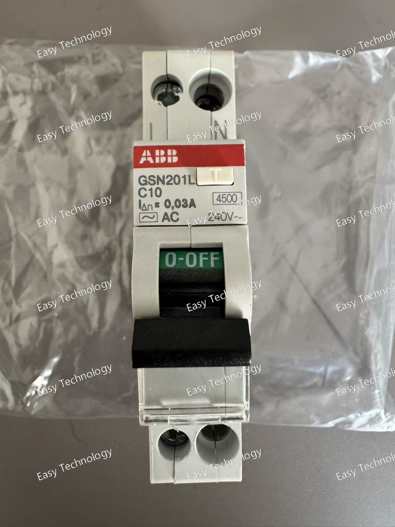
Technical Parameters Parameter Specification Notes Series / Type System Pro M - GSN Switch-Fuse Disconnector Standards IEC/EN 60947-3, IEC/EN 60947-1 Rated Operational Voltage (Ue) 690 V AC (50/60 Hz) Rated Insulation Voltage (Ui) 800 V AC Rated Impulse Withstand Voltage (Uimp) 8 kV Switch Rated Operational Current (Ie) 63 A (at 40°C, AC-23B) Frame size defined by 201. Utilization Category AC-23B (for switching motor loads) Also suitable for AC-20, AC-21, AC-22. Short-Circuit Performance • Rated Conditional Short-Circuit Current (Icq) 50 kA (with specified gG/gL NH fuses) Requires correct fuse coordination. • Rated Making Capacity (Icm) Up to 10 x Ie (peak) Fuse Compatibility • Fuse Type NH (Knife-Blade) Fuses per DIN 43620 / IEC 60269 • Fuse Size Size 00 Accepts fuse links up to 160A. • Max. Recommended Fuse Rating 100 A gG/gL (typical for thermal design) Actual depends on ambient temp and assembly. Mechanical & Electrical Life • Mechanical Durability ≥ 10,000 operations • Electrical Durability (AC-23B) ≥ 5,000 operations at full rated current Handle Type C10: Side-mounted rotary lever handle, padlockable in OFF position (up to 3 padlocks). "L" in GSN201L also indicates side-lever operation. Auxiliary Contacts Optional add-on auxiliary contact blocks (e.g., 1NO+1NC) available for signaling. Not included in base C10 version. Terminals Screw-clamp terminals for copper/aluminum cables. Mounting 35 mm DIN Rail (EN 60715) or direct panel mounting. Protection Degree IP20 (as installed in enclosure) Ambient Temperature Operating: -25°C to +60°C (derating above 40°C) Storage: -50°C to +85°C Pollution Degree PD 3 For industrial environments. Dimensions (W x H x D) Approx. 105 mm x 145 mm x 120 mm (3-pole with handle) Weight Approx. 1.2 kg (without fuses) Safety Approvals CE, cULus, CCC, etc.
Technical Parameters Parameter Category Specification Product Series G-H Series High-Performance Contactors Device Type 3-Pole AC Power Contactor Standard Compliance IEC/EN 60947-4-1, IEC/EN 60947-1 Main Circuit Ratings • Rated Operational Voltage (Ue) Up to 690 V AC, 50/60 Hz • Rated Insulation Voltage (Ui) 1000 V AC • Rated Operational Current (Ie) at AC-3 100 A (This is the typical rating for the GSH201 frame at 400V. 201 denotes the 100A frame size). Control Coil • Coil Type AC Operated (Indicated by C in -C20). • Coil Voltage Code The 20 in -C20 likely specifies a standard AC voltage. Common assignments: -C20 often corresponds to 230V AC, 50/60 Hz. (Critical Note: This must be verified with the official ABB catalog as coding can vary by region and production year.) Utilization Categories • AC-3 Squirrel-cage motors: Starting, switching off during running. Typical rating: 100 A at 400V. • AC-4 Squirrel-cage motors: Starting, plugging, inching. Rating is significantly lower (e.g., ~40-50A). • AC-1 Non-inductive or slightly inductive loads. Switching Capacity • Rated Making Capacity (Icm) Typically 1000 A (peak) at 415V AC, for handling motor inrush currents. • Rated Breaking Capacity (Icu) Typically 10-15 kA at 415V AC (with appropriate short-circuit backup protection). Endurance • Mechanical Life ≥ 10 million operations. • Electrical Life (AC-3) ≥ 1 million operations at full rated load. Power Consumption (Coil) • Pick-up (Inrush) ~1000 VA (typical for AC coil). • Holding (Sealed) ~20 VA (typical, energy-efficient design). Auxiliary Contacts Modular auxiliary contact blocks can be added (e.g., 2 NO + 2 NC). Rated typically 10A, 600V AC. Terminals Screw-clamp terminals suitable for large cable cross-sections. Mounting Can be foot-mounted on a panel or using a DIN rail adapter (optional). Ambient Temperature Operating: -25°C to +60°C (with derating above 40°C). Protection Degree IP00 (open type), must be installed in an enclosure. Approximate Dimensions ~ 155mm (L) x 130mm (W) x 120mm (H) (varies with accessories). Approximate Weight ~ 2.5 kg (base unit). Key Features • High electrical and mechanical endurance • Modular design for auxiliary contacts • Energy-saving AC magnet system • Transient suppression for AC coils • Contact position indicator
 TEL: Grace +86 13600179521
  Mail: info@hongkongeasy.com jilineasyyi@outlook.com
 Q Q:615739355
 ADDRESS:Unit 12, 20th Floor, Good View Commercial Centre, 2-16 Garden Street, Mong Kok, Hong Kong
 whats app


