
Industrial Controller
All product are in stock,guaranteed delivery within 3-7 days.


PRODUCT
PICTURE
BRAND
DESCRIBE
STOCK
DOWNLOAD
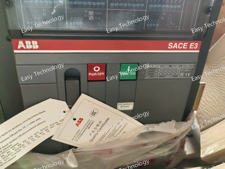
Parameter Category Specification Series / Frame ABB SACE Emax, E3 Frame Rated Operational Current (In) 2500 A Rated Operational Voltage (Ue) 690 V AC Rated Insulation Voltage (Ui) 1000 V AC Poles 3 Breaking Capacity (Icu at 400V AC) 50 kA (H version) Mounting Draw-out (Withdrawable) on a truck with safety interlocks. Trip Unit Type Thermal-Magnetic (TMD/LI or similar) - Fixed or minimally adjustable. • Long-time Protection (L) Fixed inverse-time thermal tripping characteristic. Preset to the breaker's rated current (2500A). • Short-time Protection (S) Not present. No adjustable short-time delay. • Instantaneous Protection (I) Fixed magnetic trip threshold. The R25 may indicate a specific setting (e.g., 10 x In = 25kA). • Ground-Fault Protection (G) Not included. • Adjustability Very limited or none. Cannot be fine-tuned for selective coordination. Standard Included Accessories • Draw-out Truck (W) • Electric Charging Motor (M) • Shunt Trip (MX) (P) Typical Additional (Optional) Accessories • Auxiliary Contacts (OF/SD) - Not in code, must be verified. • Undervoltage Release (MN) - Not in code, must be verified. • Closing Release (XF) - For electrical closing. Control Voltage Motor (M) and Shunt Trip (P) require an external control supply (e.g., 110V DC, 220V DC). Must be specified separately. Operation Spring-operated stored energy mechanism. Closing can be manual or electrical (if XF is installed). Communication None. Thermal-magnetic trip units do not have communication capabilities. Standards IEC 60947-2, UL 489 Typical Application Main or feeder breaker where selective coordination is not required or is handled upstream. Often used as a backup protection device or for circuits with simple protection needs.
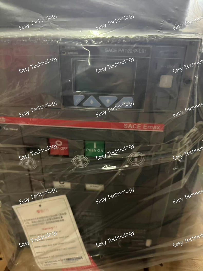
Parameter Category Specification General • Type Air Circuit Breaker (ACB), Fixed or Draw-out version (code doesn't specify; F or W needed). • Standard IEC 60947-2, UL 489 Ratings • Rated Operational Current (In) 2500 A • Rated Operational Voltage (Ue) 690 V AC • Rated Insulation Voltage (Ui) 1000 V AC • Rated Ultimate Short-Circuit Breaking Capacity (Icu) 100 kA at 400V AC (for S version). At 690V, this is lower (e.g., 75 kA). • Rated Service Short-Circuit Breaking Capacity (Ics) Typically a high percentage of Icu (e.g., 75% or 100%). Trip Unit (PR122/P) • Protection Settings L (Ir): 0.4 - 1.0 x In (1000A - 2500A) S (Isd): 1.5 - 15 x Ir, time delay adjustable (e.g., 0.05 - 0.5s) or I²t. I (Ii): 1.5 - 15 x In or OFF. • Measurement High-accuracy measurement of I, V, P, Q, S, PF, f, Energy (kWh, kVARh). Class 1. • Communication Standard RS485 port with Modbus RTU. Optional modules for Profibus, DeviceNet, Ethernet/IP, IEC 61850. • Event Logging Stores time-stamped trips, alarms, and operations. • Diagnostics Load profile, thermal memory, maintenance alerts. Mechanical • Operating Mechanism Spring-operated stored energy. Manual or electrical charging. Manual or electrical closing. • Mechanical Life ≥ 30,000 operations • Electrical Life ≥ 10,000 operations at full load Typical Included Accessories (This code lists only trip unit; accessories are separate codes like FHR NST). A typical functional unit would include: Electric motor, Shunt trip (MX), Auxiliary contacts (OF/SD), Undervoltage release (MN). Dimensions & Weight (Approx. for 3P Fixed) Width: ~ 350-450 mm, Height: ~ 550-650 mm, Depth: ~ 400-500 mm. Weight: ~ 150-200 kg.
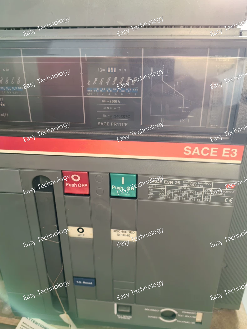
Parameter Category Specification Series / Frame ABB SACE Emax, E3 Frame Rated Operational Current (In) 2500 A Rated Operational Voltage (Ue) 690 V AC Rated Insulation Voltage (Ui) 1000 V AC Poles 3 Breaking Capacity (Icu at 400V AC) 65 kA (N version) Mounting Draw-out (Withdrawable) on a truck. Trip Unit PR11 Electronic Trip Unit Protection Functions LI (Long-time & Instantaneous only) • L (Ir): 0.4 - 1.0 x In (1000A - 2500A) adjustable. • I (Ii): Fixed or adjustable high setting (e.g., 10 x In = 25kA). • NO Short-time (S) Delay. Standard Included Accessories • Draw-out Mechanism (W) with safety interlocks. • Electric Charging Motor (M). • Shunt Trip (MX) (P) for remote opening. Typical Additional (Optional) Accessories • Auxiliary Contacts (OF/SD) for status signaling (often included but not in code; verify). • Undervoltage Release (MN). • Additional alarm contacts. Operation Spring-operated stored energy mechanism. Closing can be manual or electrical (requires separate closing release - XF). Communication The PR11 trip unit typically has limited or no communication capability. For communication, a higher-level trip unit (PR121, PR122) is required. Standards IEC 60947-2, UL 489 Typical Application Main incoming breaker for large transformers (2000-2500kVA), bus-tie breaker, or feeder for very large loads where selective coordination is achieved upstream or is not required
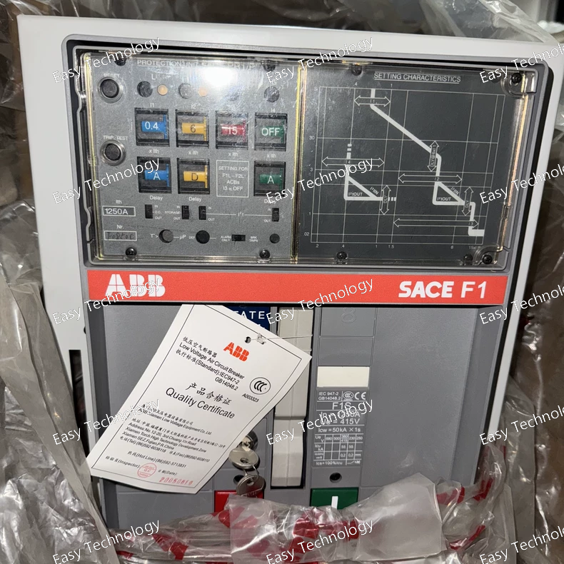
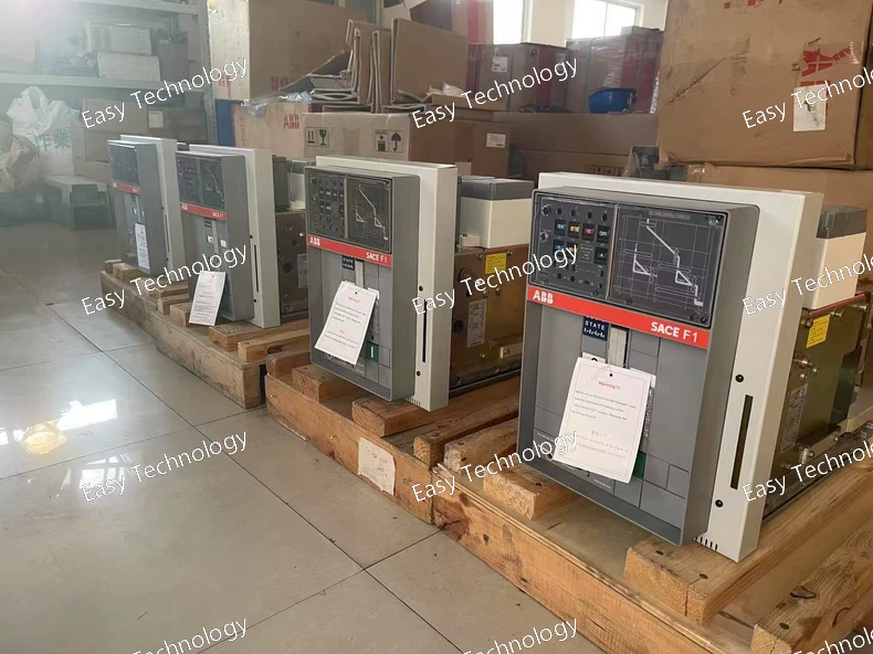
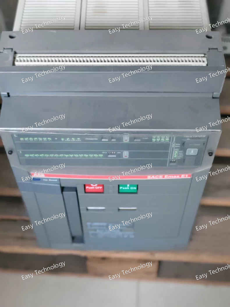
Parameter Category Specification Assembly Type Low-Voltage Switchgear Functional Unit / Feeder Compartment Standard IEC 61439-1 & -2 Internal Separation Form 1 (F1) Busbar System • Rated Current (Ibm): 1250 A • Short-Time Withstand (Icw): ~ 35-50 kA for 1s (Design dependent) Main Protective Device • Type: ABB SACE Emax E1 Frame, Fixed-mounted Air Circuit Breaker (Fixed mounting implied by code structure; W would indicate draw-out). • Rated Current (In): 1250 A • Poles: 3 • Trip Unit: Electronic (PR1 series) with display. Likely provides LSI protection (Long-time, Short-time, Instantaneous). • Breaking Capacity (Icu): Typically 50 kA at 400V AC for this configuration. Key Breaker Features & Accessories • Fixed Mounting (Integrated into the panel). • Electronic Trip Unit with local interface. • Electric Spring-Charging Motor (auto-recharge). • Shunt Trip (MX) for remote opening. • Auxiliary Contacts (OF/SD) for remote status. • Undervoltage Release (MN) for safety trip on control power loss. Control Voltage The motor and releases require an auxiliary control supply (e.g., 110V/220V DC or 230V AC) – must be specified separately. Typical Physical Configuration This describes one vertical section in a modular switchboard (e.g., MNS Digital). It includes: • The fixed E1 breaker • Busbar connections • Cable connection chamber (likely bottom or rear) • Necessary internal barriers (Form 1) IP Rating (Enclosure) Typically IP31, IP41, or IP54 depending on the overall switchgear series.
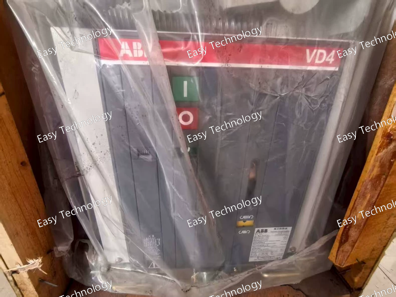
Parameter Category Specification General • Type Indoor, Vacuum, Fixed or Draw-out (depends on panel design) • Standard IEC 62271-100, ANSI C37.06 • Rated Voltage (Ur) 12 kV • Rated Frequency 50 / 60 Hz Insulation Level • Power-Frequency Withstand (Ud) 12 kV (1 min) • Lightning Impulse Withstand (Up) Typically 42 kV or 75 kV (Standard impulse withstand for 12kV class is 75 kV, but 1212 suggests a lower insulation level; this must be verified. It often corresponds to a 28 kV or 42 kV Up). Critical to confirm with actual datasheet. Current Ratings • Rated Normal Current (Ir) Common frame sizes: 630A, 1250A, 1600A, 2000A, 2500A, 3150A. The specific value is not defined in 1212-31 and must be specified separately (e.g., VD4M 1212-31 1250A). • Rated Short-Circuit Breaking Current (Isc) 31.5 kA (RMS, symmetrical) • Rated Short-Time Withstand Current (Ik) 31.5 kA for 3 seconds (typically) • Rated Peak Withstand Current (Ip) 80 kA (2.55 x Isc) Switching Performance • Rated Breaking Capacity Full Isc at Ur. Suitable for transformer, cable, and motor switching. • Mechanical Endurance ≥ 20,000 operations (M2 class) • Electrical Endurance ≥ 10,000 operations at full Ir (E2 class) Operating Mechanism (M) • Type Spring-operated, stored energy. • Charging Electric Motor for automatic spring recharging after each operation. • Closing Time ~60 – 80 ms • Opening Time ~40 – 60 ms Control & Auxiliaries • Standard Releases Interfaces with external protection relay. Equipped with Shunt Trip (MX) and Undervoltage Release (MN) as common options. • Auxiliary Contacts Multiple changeover contacts for signaling breaker status. • Control Voltage Common DC voltages: 48V, 110V, 220V DC. Must be specified. Vacuum Interrupter Axial or radial magnetic field design for long contact life and low chopping current. Dimensions & Weight Varies significantly with current rating. A 1250A fixed version approx.: • Width: ~ 400-500 mm • Height: ~ 600-700 mm • Depth: ~ 700-800 mm • Weight: ~ 150 – 250 kg
Technical Specifications Parameter Category Specification Product Series System Pro M compact - S200 Series Commercial Model S203P-C10 Standard Compliance IEC/EN 60898-1 Number of Poles & Protected Poles 1 Pole (1P). It breaks the live (phase) conductor only. Rated Current (In) 10 A Tripping Characteristic C Characteristic • Instantaneous Trip Range: 5 to 10 x In (50A to 100A). • Typical Use: General purpose applications with moderate inrush currents (e.g., lighting, household sockets, small motors). Rated Operational Voltage (Ue) 230/400 V AC Rated Insulation Voltage (Ui) 500 V AC Rated Impulse Withstand Voltage (Uimp) 4 kV Breaking Capacity (Icn) 6 kA at 230/400V AC (Standard for S203 base model). Energy Limiting Class 3 (High limiting capability) Electrical Life ≥ 20,000 cycles at rated current Mechanical Life ≥ 20,000 cycles Terminals • Screw-type terminals suitable for both rigid and flexible conductors. • Connection Capacity: 1 x 25 mm² or 2 x 1.5 - 16 mm² (with ferrule). Mounting Standard 35 mm DIN Rail (EN 60715) Ambient Temperature -25°C to +55°C (Reference calibration at 30°C) Protection Degree IP20 (When mounted in an enclosure) Approximate Dimensions (W x H x D) 18 mm x 89 mm x 69 mm (1 module width) Approximate Weight ~ 0.1 kg Certifications CE, CCC, and other international approvals. Key Features • Clear ON/OFF flag for visible contact position. • Trip-free mechanism ensures protection even if the handle is held in the ON position. • Padlockable in OFF position (with optional padlock kit).
Parameter Category Specification Assembly Type Low-Voltage Switchgear Functional Unit / Cabinet Standard IEC 61439-1 & -2 Internal Separation Form 1 (F1) - Common compartment for all live parts. Busbar System Rating • Rated Current (Ibm): 1250 A • Short-Time Withstand (Icw): Typically 35-50 kA for 1s (depends on design) • Peak Withstand (Ipk): ~2.2 x Icw Main Protective Device • Type: Emax E1 Frame, Draw-out Air Circuit Breaker • Rated Current (In): Matches or is derated from busbar, e.g., 1250A or 1000A. • Trip Unit: Electronic (PR1/P) with display. Protection functions: LSI. • Breaking Capacity (Icu): Typically 50 kA at 400V for this configuration. Key Breaker Features • Draw-out (W) for easy maintenance. • Motor Operated (M) for automatic spring charging. • Shunt Trip (P) for remote opening. • Additional accessories like auxiliary contacts (OF/SD) and undervoltage release (MN) are highly probable but not explicitly stated in this short code. Control Voltage The motor (M) and shunt trip (P) require an auxiliary control supply (e.g., 110V DC, 220V DC, or 230V AC). This must be specified separately. Typical Configuration This describes a single feeder compartment in a larger switchboard (like MNS Digital) or a standalone cabinet. It would include: • The draw-out E1 breaker • Necessary shutters and interlocks • Cable connection chambers • Local control and indication (possibly a door-mounted mimic) IP Rating (Enclosure) Typically IP31, IP41, or IP54 depending on the overall switchgear series.
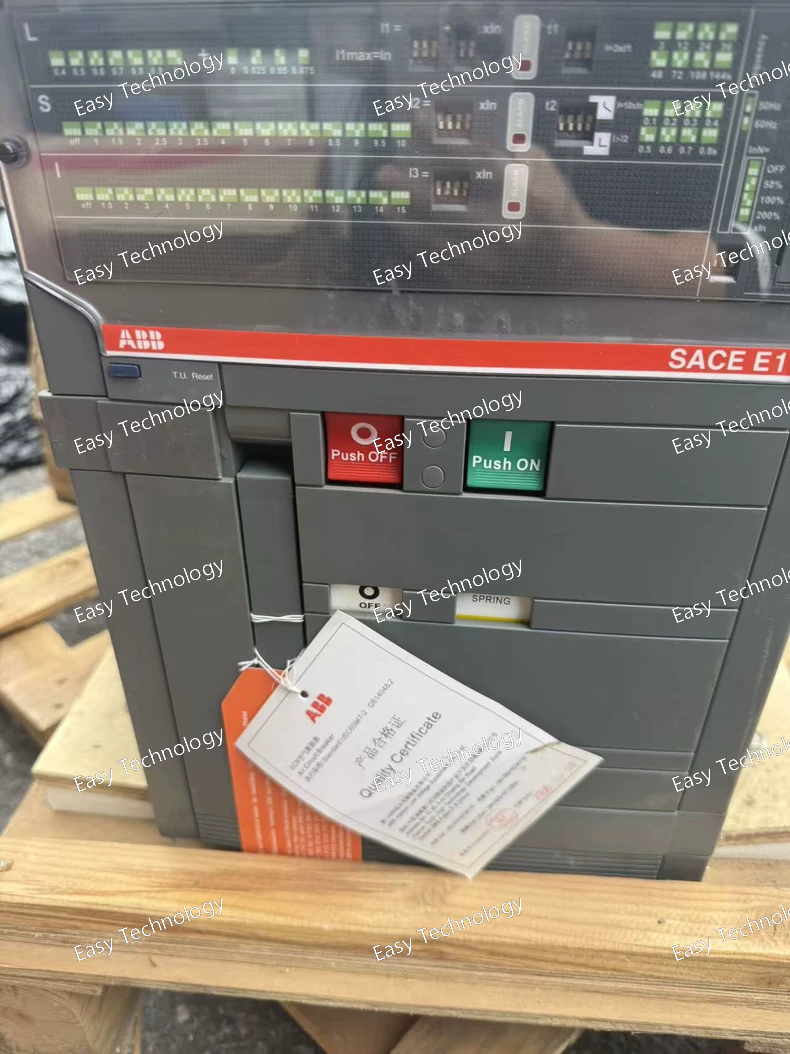
Technical Profile Parameter Category Specification Series / Frame ABB SACE Emax, E1B Frame Rated Operational Current (In) 1250 A Rated Operational Voltage (Ue) 690 V AC Rated Insulation Voltage (Ui) 1000 V AC Poles 3 Breaking Capacity (Icu at 400V AC) 50 kA (F version) Mounting Fixed Trip Unit PR121 Electronic Trip Unit Protection Functions LSI • L (Ir): 0.4 - 1.0 x In (500A - 1250A) adjustable. • S (Isd): 1.5 - 10 x Ir adjustable. Time delay adjustable. • I (Ii): 2 - 14 x In adjustable or OFF. Standard Included Accessories • Shunt Trip (MX) for remote opening. • Auxiliary Contacts (OF/SD) 2NO+2NC for status. • Undervoltage Release (MN) for loss-of-voltage tripping. Termination Front Terminals for power connection. Operation Spring-operated stored energy mechanism. Manual or electrical charging. Manual or electrical closing. Communication (Optional) The PR121 trip unit can be equipped with an optional communication module (Ekip Com) for Modbus, Profibus, etc. Standards IEC 60947-2, UL 489
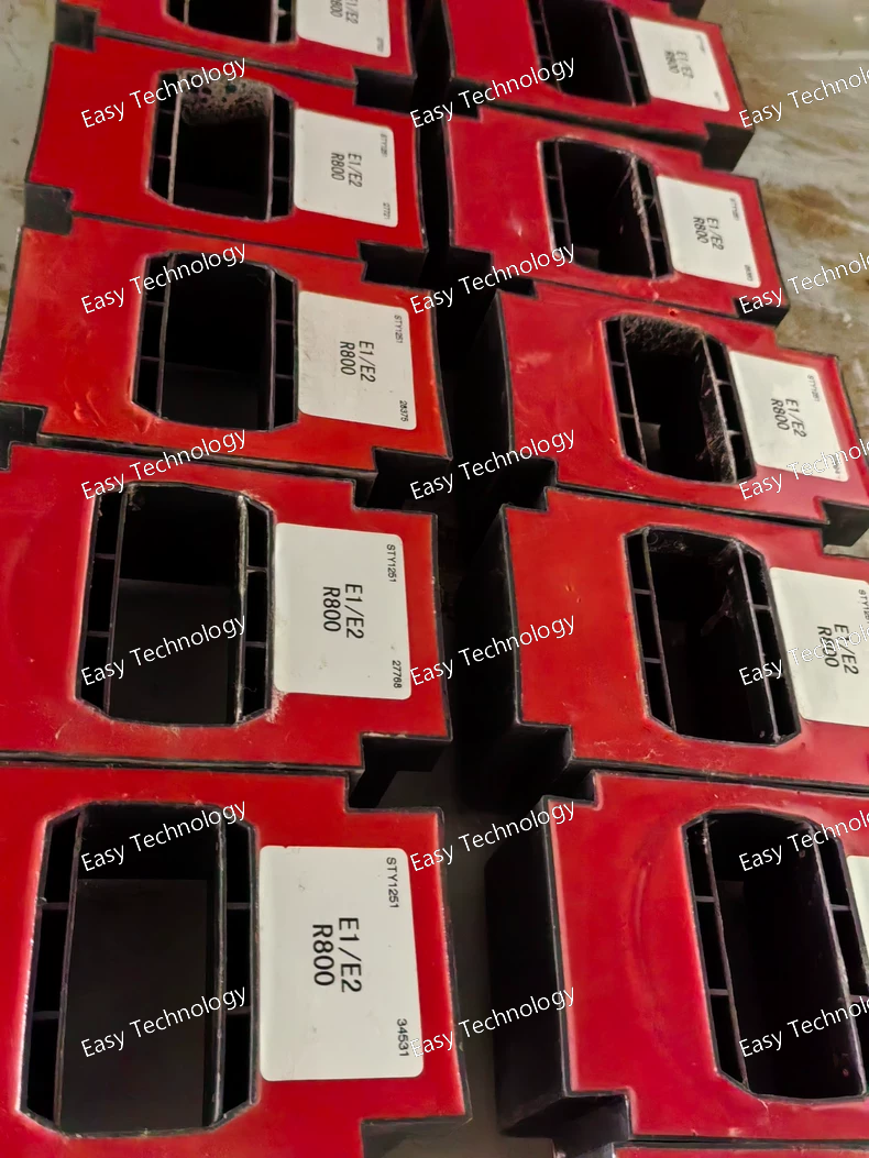
Technical Parameters: E1 vs. E2 Frames Parameter Category E1 Frame E2 Frame Frame Size Code E1 E2 Rated Ultimate Current (Iu) Up to 1600 A Up to 2000 A (Common) / 2500 A (E2.5 variant) Typical Model Examples E1.1 (800A), E1.2 (1000A), E1.3 (1250A), E1.4 (1600A) E2.1 (1600A), E2.2 (2000A), E2.3 (2500A), E2.4 (3200A), E2.5 (4000A), E2.6 (5000A), E2.7 (6300A) Rated Operational Voltage (Ue) 690 V AC (Both frames) Breaking Capacity (Icu) - Example at 400V AC High (H) Version: 50 kA, Normal (N) Version: 65 kA, High (S) Version: 100 kA (Varies by specific model and trip unit). High (H) Version: 70 kA, Normal (N) Version: 85 kA, High (S) Version: 100-150 kA (Varies, E2 frames offer higher ratings). Trip Units (Common Types) Electronic: PR121, PR122, PR123. Thermal-Magnetic: TMD, TMA, MIC2.0, MIC5.0, MIC6.0 (Deprecated). Operating Mechanism Spring-operated stored energy mechanism. Manual or electrical charging. Manual or electrical closing/opening. Mounting Style Fixed (Standard) or Draw-out (Plug-in) versions available. Draw-out versions allow easy maintenance and testing without disconnecting power cables. Poles 3-Pole or 4-Pole versions available. Communication Via electronic trip units (e.g., PR122/P) with optional communication modules (e.g., Ekip Com) for Modbus, Profibus, Ethernet/IP, etc. Key Physical Difference Smaller physical size, lighter weight, designed for lower current applications. Larger physical size, more robust construction to handle higher currents and forces. Typical Application • Main incomer for medium-sized transformers (e.g., 1000-1250 kVA). • Large feeder protection. • Large motor protection. • Main incomer for large transformers (e.g., 1500-2500 kVA). • Bus-tie breaker in large switchboards. • Generator main breaker. • Protection of very high power loads. Approx. Dimensions (W x H x D) for 3P Fixed ~ 260mm x 400mm x 300mm (Varies by model) ~ 300-400mm x 500-600mm x 350-450mm (Larger for higher current variants) Approx. Weight for 3P Fixed ~ 45 - 70 kg ~ 80 - 150 kg
Technical Specifications Parameter Category Specification Product Type Split-Core (Wrapping-Type) Current Transformer Standard IEC 61869-2 (Measuring Transformers) Rated Primary Current (Ipn) 300 A Rated Secondary Current (Isn) 1 A or 5 A (The exact secondary current is a key variant. This code likely specifies one, with R1 potentially indicating 1A. The product label will confirm.) Accuracy Class Typically Class 1 or Class 0.5 for measurement. Common for this type is 1.0 (1%). Rated Output (VA) Commonly 2.5 VA or 5 VA at the specified accuracy class. Accuracy Limit Factor (ALF) Typically 5 (for measurement purposes, not protection). Frequency 50/60 Hz Rated Insulation Voltage 0.72 / 3 kV (Category III, for installation on systems up to 1000V AC). Core Construction Split-core, with a secure latching or screw-clamping mechanism. Window Diameter / Size A key physical parameter determining the maximum conductor size it can accommodate. Common sizes are Ø50mm, Ø65mm, or rectangular openings (e.g., 80x30mm). Mounting Can be mounted via integrated lugs, DIN rail clip (optional), or simply secured around the conductor. Connections Secondary terminals are typically screw-type for secure connection of measurement wires. Ambient Temperature -25°C to +70°C (Operating) Safety Standard Designed for connection to secondary circuits which are normally earthed. The secondary must NEVER be left open-circuited under load. Typical Use Connecting to: • Multi-function energy meters (e.g., ABB B23, B24 series) • Power quality analyzers • Building Management System (BMS) inputs • SCADA system transducers
Technical Parameters Parameter Category Specification Compatible Breaker Series ABB SACE Tmax XT Molded Case Circuit Breakers (MCCBs) - Fixed and Plug-in versions. (Also compatible with some earlier T, TL, and XT1 breakers with appropriate adapters). Rated Frame Current (In) Must match the Tmax XT frame size. Compatible with multiple frames, typically from XT1 (160A) to XT4 (630A). The PR121/P is scaled; its settings adjust based on the installed breaker's frame size. Power Supply Self-powered from the breaker's internal current sensors. No external auxiliary power required for protection and basic functions. Core Protection Functions • Long-time Protection (L) Adjustable Settings: - Ir (Rated Current): 0.4 to 1.0 x In (in steps). - tr (Time Delay): Adjustable via selection of I²t inverse-time curves (e.g., Curve 1, 2, 3). • Short-time Protection (S) Adjustable Settings: - Isd (Short-time Current): 1.5 to 10 x Ir (in steps). - tsd (Short-time Delay): Adjustable in seconds (e.g., 0.1s or 0.2s) or can be set to OFF. • Instantaneous Protection (I) Adjustable Settings: - Ii (Instantaneous Current): 2 to 14 x In, or can be set to OFF. • Ground-Fault Protection (G) Available. Adjustable Settings: - Ig (Ground Fault Current): 0.2 to 1.0 x In (or fixed steps like 100A, 200A...). - tg (Ground Fault Delay): Adjustable in seconds (e.g., 0.1s, 0.2s, 0.3s) or INST (instantaneous). Measurement & Display (/P Feature) • Display Backlit LCD display (monochrome). • Measured Values Real-time display of: Phase currents (L1, L2, L3), Neutral current (if sensor present), Max current, % Load. Communication Optional. Requires an add-on communication module (e.g., Ekip Com module) to enable Modbus RTU, Profibus DP, or DeviceNet. Diagnostics & Logging • Pre-alarms for overload (e.g., 90%, 105%). • Trip Cause Indication on display (e.g., L, S, I, G). • Last Fault Value recording. Configuration Via front keypad or via ABB Ekip Connect PC software (requires optional USB or communication module). Ambient Temperature -25°C to +70°C (Operating) Standards IEC 60947-2, UL 489 Key Feature Selectivity (Coordination): The adjustable Isd and tsd (S function) allow for time-current selectivity with downstream breakers. The adjustable Ii (I function) can be used for current selectivity.
Technical Specifications Parameter Category Specification Product Line / Series ABB SACE Emax (E4 Frame) Device Type Fixed-Mounted Air Circuit Breaker (ACB) Model Code Breakdown L = Fixed Thermal-Magnetic Trip Unit (TMD) 40 = E4 Frame Size Code 25 = Rated Current (In) = 2500 A H = Breaking Capacity = High (Typically 70 kA Icu at 400V AC) Standard Compliance IEC 60947-2, UL 489 Rated Operational Voltage (Ue) 690 V AC Rated Insulation Voltage (Ui) 1000 V AC Rated Ultimate Short-Circuit Breaking Capacity (Icu) 70 kA at 400V AC (for "H" version). At 690V AC, this rating is lower (e.g., 50 kA). Rated Service Short-Circuit Breaking Capacity (Ics) Typically 100% of Icu (e.g., 70 kA) for category Ics = Icu. Rated Operating Current (In) 2500 A (Continuous, at 40°C ambient). Trip Unit Type Fixed Thermal-Magnetic (TMD/LI - "L" in model) • Long-Time Protection (L) Fixed inverse-time thermal tripping characteristic. Threshold is preset to the breaker's rated current (2500A). • Short-Time Protection (S) Not adjustable (fixed magnetic trip). The "I" in LI indicates an Instantaneous-only magnetic trip for high-level short-circuits. No adjustable short-time delay. • Instantaneous Protection (I) Fixed threshold, typically at a high multiple of In (e.g., ~10xIn). • Ground-Fault Protection Not included in standard L version. Control & Accessories • Standard Operating Mechanism Manual charge spring (stored energy), with manual ON/OFF handle. Can be equipped with an electric motor for remote electrical closing (common option). • Shunt Trip (MX) Optional, for remote electrical tripping. • Undervoltage Release (MN) Optional, for automatic tripping on loss of control voltage. • Auxiliary Contacts (OF/SD) Optional, for signaling breaker status (ON/OFF/Tripped). Mechanical & Electrical Life • Mechanical Endurance ≥ 20,000 operations • Electrical Endurance ≥ 5,000 operations at full rated current Mounting Fixed installation in switchgear compartments. It is not draw-out. Connection Front or rear horizontal/vertical power connections for busbars or large cables. Poles 3-Pole or 4-Pole versions available (model code may differ for 4P). Dimensions (Approx. for 3P) Width: ~ 300-400 mm, Height: ~ 400-500 mm, Depth: ~ 300-400 mm (Varies). Weight (Approx.) ~ 80 - 120 kg Ambient Temperature Operating: -5°C to +40°C (Derating above 40°C applies)
 TEL: Grace +86 13600179521
  Mail: info@hongkongeasy.com jilineasyyi@outlook.com
 Q Q:615739355
 ADDRESS:Unit 12, 20th Floor, Good View Commercial Centre, 2-16 Garden Street, Mong Kok, Hong Kong
 whats app


