
Industrial Controller
All product are in stock,guaranteed delivery within 3-7 days.


PRODUCT
PICTURE
BRAND
DESCRIBE
STOCK
DOWNLOAD
Parameter Category Specification System / Standard KNX / EN 50090, ISO/IEC 14543 Bus Voltage 21 – 32 V DC (KNX SELV) Auxiliary Supply (Us) 24 V AC/DC, SELV (Typical for valve actuators and fan speed relays) Core HVAC Control Functions • Room Temperature Control: Compares measured room temperature (via integrated or external sensor) with setpoint. • Fan Speed Control: 3-speed (High/Med/Low) or 4-speed (including Auto) via relay outputs. • Valve Control: Modulating control of water valves via 0-10V analog outputs for precise flow regulation in 2-pipe or 4-pipe systems. • Operating Mode Selection: Auto, Comfort, Standby, Frost Protection, etc. Inputs & Sensors • Integrated Room Temperature Sensor (likely due to E suffix). • Binary Inputs (AB): For window contacts, presence detectors, local push-buttons. • Optional External Sensors: Can connect to external temperature sensors (e.g., floor sensor) via KNX or analog input. Outputs • Analog Outputs (AE): 2 channels of 0-10V DC for controlling heating valve and cooling valve actuators (in a 4-pipe system). • Relay Outputs (AG): Typically 3 or 4 relays for fan speed control (High, Medium, Low, possibly Off). Each relay rated for fan motor load (e.g., 5(2)A @ 230V AC). • Additional Auxiliary Relay: May include one for On/Off valve or summer/winter changeover. KNX Communication • Sends room temperature, operating mode, fan speed, valve position, alarms. • Receives setpoints, mode commands, schedules from higher-level systems. • Can be part of energy management scenes (e.g., night setback). User Interface Likely includes a basic local display (showing temperature/setpoint) and buttons for manual override (if E indicates this feature). Configuration Exclusively via ABB ETS (Engineering Tool Software). Extensive parameters for: PID control loops, valve characteristics, fan speed logic, interlock with window contacts, hysteresis, etc. Mounting 35 mm DIN Rail in a distribution board, typically located near the fan coil unit. Typical Wiring Connects to: KNX bus, 24V AC/DC power supply, fan motor terminals, valve actuator cables, window contact, and optionally an external temperature sensor.
Parameter Category Specification System / Standard KNX / EN 50090, ISO/IEC 14543 Bus Voltage 21 – 32 V DC (KNX SELV) Auxiliary Supply (Us) 230 V AC, 50/60 Hz Typical Channel Configuration Based on KAEADAB, it may combine: • 4 independent channels capable of being configured as: - Dimmable lighting output (0-10V control signal). - Switchable lighting output (via relay, e.g., 16A). - Shutter/Blind output (with Up/Down/Stop control and position feedback). Output Relays (if present) • Contact Type: Changeover (SPDT). • Rated Load (AC-1): Typically 16 A / 230 V AC. Analog Outputs (for Dimming) • Type: 0-10 V DC reference signal. • Load: For controlling electronic ballasts (EVG) or LED drivers. Binary Inputs • Quantity: Likely 4 or more. • Type: Dry contact or voltage pulse (from pushbuttons). • Function: Configurable as switch, push-button, scene call, etc. Shutter Control Features • Control: Up, Down, Stop, Step, Position control (%). • Feedback: Can monitor and report position via KNX. • Safety: Integrated anti-jamming protection (if supported). Logic & Scenes Built-in logic for: • Central ON/OFF commands. • Lighting scenes (multiple channels recalled simultaneously). • Time-based control (via external KNX time scheduler). Status Indication LED per channel, bus status LED. Mounting 35 mm DIN Rail (EN 60715) in a distribution board. Configuration Exclusively via ABB ETS (Engineering Tool Software) using the device's specific database file. Typical Use Controlling a mixed zone containing: • Dimmable ceiling lights (via 0-10V output). • On/Off wall lights or sockets (via relay). • Motorized blinds on the windows (via shutter output). All controlled by KNX wall switches (connected to binary inputs) or a building management system.
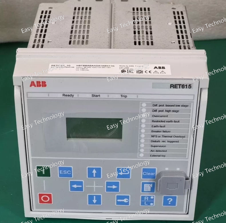
Technical Parameters Parameter Category Specification Product Series / Platform ABB Relion® 615 Series (Transformer Protection Platform) Device Type Numerical Transformer Protection and Control Relay (IED) Hardware Variant Suffix • -E: Wide-range auxiliary power supply (e.g., 48-250V DC / 48-240V AC). • -1G: Specific hardware package defining the number and type of I/O modules, communication ports, and possibly analog input configurations. 1G often indicates a standard or common configuration for transformer applications. Key Standards IEC 60255, IEC 61850 (Ed. 2), IEC 60870-5-103 Rated Auxiliary Supply (Us) 48 - 250 V DC / 48 - 240 V AC, 50/60 Hz (Auto-ranging, typical for -E). Analog Inputs (Typical) Designed for Dual-CT Sets: • HV Side: 3 phase currents (I1, I2, I3) + 1 neutral current. • LV Side: 3 phase currents (I4, I5, I6) + 1 neutral/ground current. • Configurable for 1 A or 5 A secondary. • Voltage Inputs: 3 phase voltages (for HV or LV side metering/protection) + 1 residual voltage. Core Protection Functions Transformer-Specific Suite: • Differential Protection (87T): High-impedance or percentage restrained, with harmonic restraint for inrush and overexcitation. • Restricted Earth Fault (REF) Protection (87N): For both HV and LV windings. • Overcurrent Protection (50/51, 50N/51N): Backup protection for HV and LV sides. • Thermal Overload Protection (49): For transformer winding and oil. • Over/Under Voltage (27/59) & Frequency (81). • Buchholz & Sudden Pressure Relay Interface. • Circuit Breaker Failure (50BF). Control & Automation • Integrated Bay Control: For HV and LV circuit breakers, isolators, and tap changers. • Programmable Logic (CFC): Extensive logic for interlocking, sequencing, and automation. • Voltage-based Auto-Reclosing (79) and Synchronization (25). Measurement & Metering High-accuracy (Class 0.5) measurement of currents, voltages, power (P, Q, S), power factor, frequency, energy, and harmonics on both sides of the transformer. Human-Machine Interface (HMI) • Large graphical LCD. • Intuitive keypad. • Status LEDs. • Front USB port. Data Recording • Event Recorder (≥ 2000 events). • Disturbance Recorder (Multiple analog and binary channels). Communication Interfaces As per -1G package, typically includes: • Multiple Ethernet ports for IEC 61850-8-1 (GOOSE/MMS) and station bus. • RS485 serial port(s) for legacy protocols (IEC 60870-5-103, Modbus RTU). (Exact ports depend on the -1G definition). Time Synchronization IRIG-B, SNTP, PTP (IEEE 1588) support. Operating Temperature -40°C to +70°C (Extended range, typical for -E version). Mounting Panel-mounted. Configuration Software ABB PCM600. Typical Applications Protection of two-winding power transformers in: • Utility transmission and distribution substations. • Industrial plants (steel, cement, mining). • Renewable energy plants (solar, wind farm step-up transformers). • Data centers and critical infrastructure.
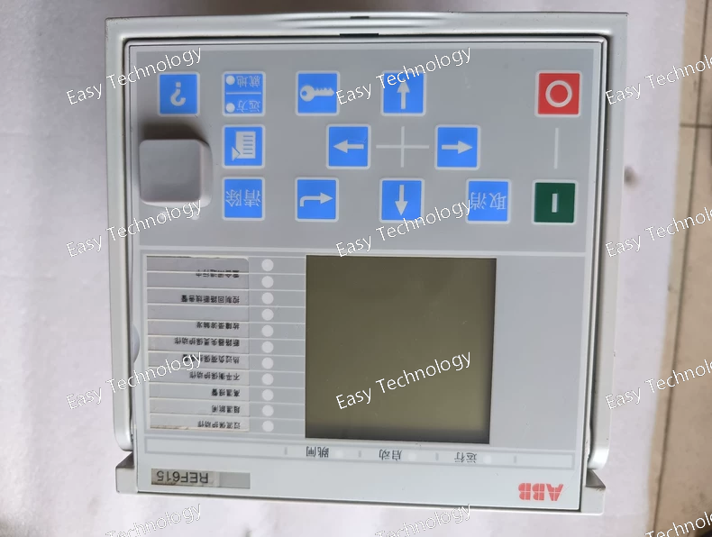
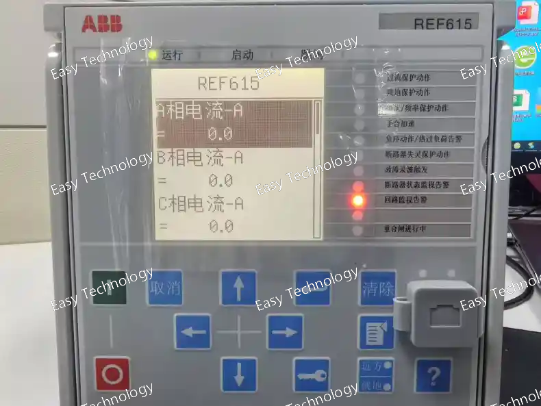
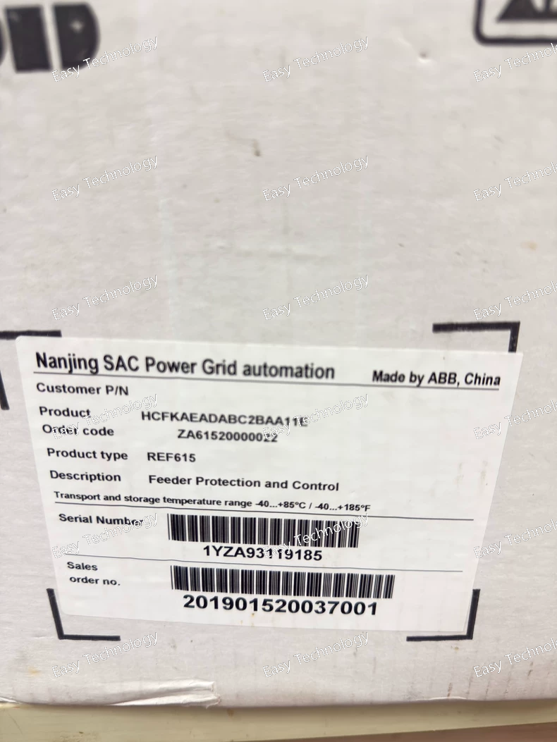
Technical Parameters Parameter Category Specification Product Series / Platform ABB Relion® 615 Series (REF615 Platform) Device Type Numerical Feeder Protection and Control Relay (IED) Hardware Variant Suffix -D - Defines the auxiliary power supply range: 48-110 V DC. Key Standards IEC 60255, IEC 61850 (Ed. 2), IEC 60870-5-103 Rated Auxiliary Supply (Us) 48 - 110 V DC (This is the defining characteristic of the -D version). Analog Inputs • Current (CT) Inputs 5 current inputs (3 phase + 1 neutral + 1 sensitive earth). Configurable for 1 A or 5 A secondary. • Voltage (VT) Inputs 4 voltage inputs (3 phase + 1 residual). Typical ratings: 100/110 V or 100/√3 V. Core Protection Functions Comprehensive suite (software-configurable): • Directional/Non-directional overcurrent (50/51, 67) • Earth-fault protection (50N/51N, 67N) • Negative sequence overcurrent (46) • Thermal overload (49) • Over/Under voltage (27/59) & frequency (81) • Auto-reclosing (79) • Circuit breaker failure (50BF) Control & Automation • Control of switching devices (CB, disconnectors). • Programmable logic (CFC). • Synchrocheck (25). Measurement & Metering Class 0.5 for I, V, P, Q, S, PF, f, Energy, Harmonics. Human-Machine Interface (HMI) • Graphical LCD with backlight. • Keypad. • LED indicators. • Front USB port. Data Recording • Event recorder. • Disturbance recorder (fault oscillography). Communication Interfaces Base unit typically includes: • 1 x RS485 port (for IEC 60870-5-103 / Modbus RTU). • 1 x Ethernet port (RJ45). Optional plug-in modules for IEC 61850, IEC 60870-5-104, etc. Time Synchronization Supports IRIG-B, SNTP. Operating Temperature Standard Range: -25°C to +55°C (or -40°C to +70°C depending on specific -D variant; refer to datasheet). Mounting Panel-mounted. Configuration Software ABB PCM600. Typical Ordering Code A full code is longer, e.g., REF615C-D A5D1A1B1B1B5C..., specifying CT/VT ratings, I/O, and communication options.
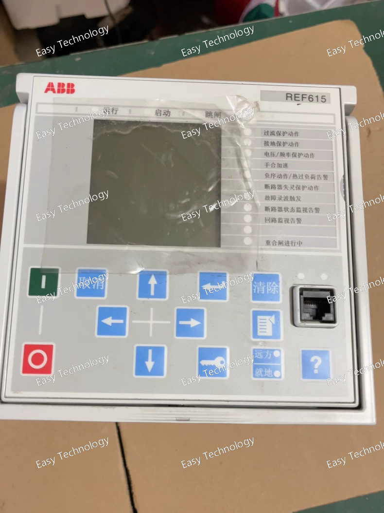
Technical Parameters Parameter Category Specification Product Series / Platform ABB Relion® 615 Series (REF615 Platform) Device Type Numerical Feeder Protection and Control Relay (IED) Hardware Variant Suffix -E - Typically indicates: • Wide-range auxiliary power supply. • Extended operating temperature range. • Possibly a specific default I/O or communication configuration. Key Standards IEC 60255, IEC 61850 (Ed. 2), IEC 60870-5-103 Rated Auxiliary Supply (Us) Typical for -E version: 48 - 250 V DC / 48 - 240 V AC, 50/60 Hz (Auto-ranging). This is a key benefit, allowing installation in systems with various control voltages. Analog Inputs • Current (CT) Inputs 5 current inputs: 3 phase (IL1, IL2, IL3), 1 neutral (IN), 1 sensitive earth fault (Io). Configurable for 1 A or 5 A secondary. • Voltage (VT) Inputs 4 voltage inputs: 3 phase (UL1, UL2, UL3) + 1 residual/auxiliary voltage (Uo). Standard ratings: 100/110 V or 100/√3 V. Core Protection Functions Full suite included (configurable via software): • Directional/Non-directional phase & earth overcurrent (50/51, 67) • Two-step negative sequence overcurrent (46) • Thermal overload (49) • Over/Under voltage (27/59) & frequency (81) • Auto-reclosing (79) • Breaker failure (50BF) • Sensitive directional earth fault (67N) Control & Automation • Control of up to 5 switching devices (CB, disconnectors). • Programmable logic (CFC in PCM600). • Synchrocheck (25). Measurement & Metering Class 0.5 for: I, V, P, Q, S, PF, f, Energy (kWh, kVARh), Harmonics. Human-Machine Interface (HMI) • Graphical LCD with backlight. • Keypad navigation. • LED indicators. • Front USB port. Data Recording • Event recorder (>1000 events). • Disturbance recorder (oscillography). Communication Interfaces Base unit typically includes: • 1 x RS485 port (for IEC 60870-5-103 or Modbus RTU). • 1 x Ethernet port (RJ45, front or rear). Optional plug-in modules for: IEC 61850, IEC 60870-5-104, additional Ethernet, Profibus, etc. Time Synchronization IRIG-B, SNTP, PTP (IEEE 1588) support. Operating Temperature Extended Range: -40°C to +70°C (A key feature of the -E variant). Mounting Panel-mounted (compact design). Configuration Software ABB PCM600. Typical Ordering Context A complete order code would be longer, e.g., REF615C-E A5D1A1B1B1B5C..., where the subsequent letters/numbers define: CT/VT ratings, binary I/O count, communication modules, etc.
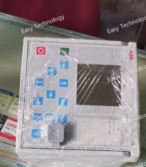
Technical Parameters Parameter Category Specification Product Series / Platform ABB Relion® 615 Series Device Type Numerical Feeder Protection and Control Relay (IED) Key Standards IEC 60255, IEC 61850 (Ed. 2), IEC 60870-5-103 Rated Auxiliary Supply (Us) 24-48 V DC, 48-250 V DC, 110-240 V DC/AC (Multiple versions available, e.g., -A, -D, -G suffixes). Analog Inputs • Current (CT) Inputs 5 current inputs: 3 phase (IL1, IL2, IL3), 1 neutral/earth (IN), 1 sensitive earth fault (optional, via core-balance CT). Configurable for 1 A or 5 A secondary. • Voltage (VT) Inputs 4 voltage inputs: 3 phase-to-earth voltages (UL1, UL2, UL3) + 1 residual voltage (U0) or an additional busbar voltage for synchrocheck. Typical ratings: 100/110 V or 100/√3 V. Core Protection Functions Comprehensive suite including: • Three-phase non-directional/directional overcurrent (50/51, 67) • Earth-fault protection (50N/51N, 67N) – sensitive & residual • Two-step negative-sequence overcurrent (46) for unbalance • Two-step thermal overload (49) for cables/transformers • Two-step over/under voltage (27/59) • Two-step over/under frequency (81) • Auto-reclosing (79) for overhead lines • Circuit breaker failure protection (50BF) Control & Interlocking • Bay control for up to 5 objects (e.g., CB, 2 disconnectors, 2 earthing switches). • Programmable logic with CFC (Continuous Function Chart) editor in PCM600. • Synchronism check (25) and live/dead line monitoring. Measurement & Metering High-accuracy measurement (Class 0.5) of: • Currents, Voltages (fundamental & true RMS) • Power (P, Q, S), Power Factor, Frequency • Energy (Import/Export, kWh, kVARh) • Harmonics (up to 15th) Human-Machine Interface (HMI) • Large graphical LCD with backlight. • Navigation keys and function keys. • LED indicators for status, alarms, and trips. • Front USB port for configuration and data extraction. Data Recording • Event recorder (≥ 1000 time-stamped events). • Disturbance recorder (fault recorder/oscillography) with analog channels and binary signals. Communication Interfaces • Rear communication slots: Supports plug-in modules for: - IEC 61850-8-1 (GOOSE, MMS) over Ethernet (copper/fiber) - IEC 60870-5-103/104, Modbus RTU/TCP, DNP3 • Front port: Ethernet (RJ45) for engineering access. Time Synchronization Supports SNTP, IRIG-B, and PTP (IEEE 1588). Operating Temperature -40°C to +70°C (Extended range) Mounting Panel-mounted (DIN rail or direct mounting). Compact dimensions. Configuration Software ABB PCM600 – Universal protection and control IED engineering tool. Typical Applications • Overhead line and cable feeder protection in distribution substations. • Transformer protection (for small-mid size transformers). • Capacitor bank protection and control. • Industrial plant feeder protection.
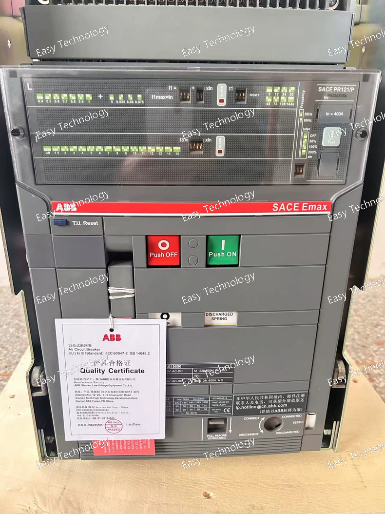
Parameter Category Specification Series / Frame ABB SACE Emax, E1 Frame (E1.2) Rated Operational Current (In) 1000 A (Frame rating). Trip setting (Ir) adjustable down to ~400A (per R400 code interpretation). Rated Operational Voltage (Ue) 690 V AC Rated Insulation Voltage (Ui) 1000 V AC Poles 3 Breaking Capacity (Icu at 400V AC) 65 kA (N version) Mounting Draw-out (Withdrawable) on a truck. Trip Unit PR121/P Electronic Trip Unit Protection Functions LI (Long-time & Instantaneous only) • L (Ir): Adjustable, likely range 0.4 - 1.0 x In (400A - 1000A). The R400 may set a base. • I (Ii): Adjustable (e.g., 2 - 14 x In) or OFF. • NO Short-time (S) Delay. Standard Included Accessories • Draw-out Truck (W) with safety interlocks. • Handle/Door Coupling Kit (H). • Shunt Trip (MX) (R) for remote opening. Typical Additional (Optional) Accessories • Electric Charging Motor (M) - NOT in code. Must verify if included. • Auxiliary Contacts (OF/SD) - NOT in code. Must verify. • Undervoltage Release (MN) - NOT in code. Must verify. Control Voltage Shunt Trip (R) requires an external control supply (e.g., 110V DC, 220V DC, 230V AC). Must be specified separately. Operation Spring-operated stored energy mechanism. Closing can be manual or electrical (requires separate closing release - XF). Charging is likely manual unless Motor (M) is specified. Communication The PR121/P trip unit supports communication via an optional add-on module (Ekip Com) for Modbus, Profibus, etc. Standards IEC 60947-2, UL 489 Typical Application Feeder protection for large loads or sub-distribution where instantaneous tripping is acceptable and selective coordination is provided upstream or is not critical.
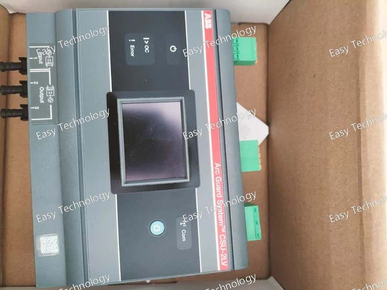
Parameter Category Specification Parent System Designed for integration into ABB UniGear ZS1 or similar MV switchgear panels. Input Power Supply • Voltage: Typically accepts a 3-phase + Neutral input from an external LV source. Common ratings: 400V AC, 50/60 Hz or 480V AC, 60 Hz. • Connection: Via terminal blocks or plug-in connector at the rear of the unit. Core Components (Typical) 1. Main LV Incoming Switch/Isolator: A miniature circuit breaker (MCB) or molded case switch for isolation and protection of the entire CSU. 2. Control Transformer(s): Steps down voltage to standard control voltages (e.g., 230V AC, 120V AC, 110V AC, 24V DC). 3. Distribution & Protection: Multiple outgoing circuits protected by MCBs or fuses for: - Heating & Dehumidification (H) - Lighting (L) - Socket Outlets (S) - Protection & Control Relays (Prot) - Motor Operating Mechanisms (for circuit breakers/disconnectors) 4. Terminal Blocks: For connecting external field wiring to the distributed services. Output Circuits (Typical) • AC Power Outlets: 1-Phase, 230V (e.g., for soldering iron, test equipment). • DC Power Supply: 24V DC or 48V DC for protection relays, PLCs, and electronic devices. • Heating Circuit: 230V AC for space heater to prevent condensation. • Lighting Circuit: 230V AC or 120V AC for internal panel lighting. • Auxiliary Supply: For spring charging motors, indicator lamps. Mounting Mounts on a dedicated draw-out chassis or fixed rails inside a standard UniGear compartment (often below the relay compartment). Connection Plug-in or fixed wiring to the MV panel's internal wiring harness. Safety Features • Clear segregation of circuits. • Individual protection for each outgoing circuit. • Door interlock possible for the main isolator. • Insulated covers and shrouds. Physical Dimensions Compact, designed to fit within a standard UniGear module width (e.g., 350mm, 400mm, 500mm). Benefits • Standardization: Ensures consistent auxiliary power design across all panels. • Safety: Centralized, properly protected LV distribution reduces wiring errors and hazards. • Maintenance: Entire unit can be easily accessed, tested, or replaced. • Documentation: Supplied with clear wiring diagrams.
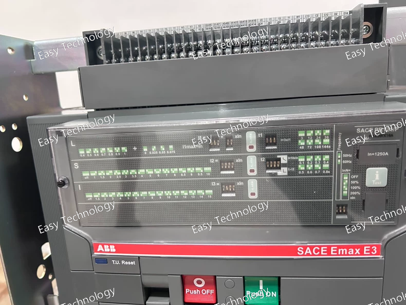
Parameter Category Specification Series / Frame ABB SACE Emax, E3 Frame Rated Operational Current (In) 1250 A (Continuous current at 40°C ambient). This typically corresponds to the E3.2 or E3.3 specific model within the E3 frame. Rated Operational Voltage (Ue) 690 V AC Rated Insulation Voltage (Ui) 1000 V AC Breaking Capacity (Icu) - Options Must be specified. Common options for E3 frame: • H (High): 50 kA at 400V AC • N (Normal): 65 kA at 400V AC (A common balanced choice) • S (Super): 100 kA at 400V AC (For high fault level areas) Poles Typically 3-Pole or 4-Pole. Trip Unit Options (Critical Selection) • Electronic (Recommended for flexibility): - PR121/P: Basic electronic unit with LSI protection, measurement, and comms option. - PR122/P: Most common advanced choice for full protection (LSI), advanced measurement, logging, and communication. • Thermal-Magnetic: For fixed, non-adjustable protection (e.g., TMD-LI). Lower cost, less functionality. Mounting Style • Fixed (F): Permanently wired into the panel. Lower cost. • Draw-out (W): Highly recommended for maintenance. Allows breaker to be isolated, tested, and replaced without disturbing main busbars. Operating Mechanism Spring-operated stored energy mechanism. Can be manual or electrically charged. Standard Accessories (Configurable) Typically selected as a package (e.g., FHR NST): • Electric charging motor (M) • Shunt trip (MX) for remote opening • Auxiliary contacts (OF/SD) for status signaling (e.g., 2NO+2NC) • Undervoltage release (MN) for safety trip on control power loss Communication Available with PR121/P and PR122/P electronic trip units via plug-in modules (Modbus RTU, Profibus DP, Ethernet/IP, etc.). Mechanical Life ≥ 30,000 operations Electrical Life ≥ 10,000 operations at full rated current Short-Time Withstand Current (Icw) Typically equals the Icu rating for 1 second (e.g., 65 kA for 1s). Dimensions (Approx. for 3P Fixed) Width: ~ 300-350 mm Height: ~ 500-550 mm Depth: ~ 350-400 mm Weight (Approx. for 3P Fixed) ~ 120 - 160 kg
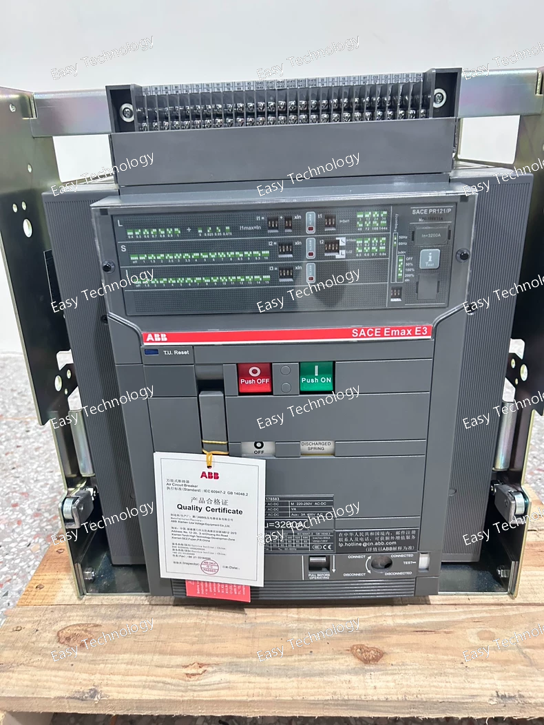
Parameter Category Specification Series / Frame ABB SACE Emax, E3 Frame Rated Operational Current (In) 3200 A (Continuous current at 40°C ambient). This corresponds to the E3.4 specific model within the E3 frame. Rated Operational Voltage (Ue) 690 V AC Rated Insulation Voltage (Ui) 1000 V AC Breaking Capacity (Icu) - Options Must be specified. Common options for E3 frame: • H (High): 50 kA at 400V AC • N (Normal): 65 kA at 400V AC • S (Super): 100 kA at 400V AC Poles Typically 3-Pole or 4-Pole. Trip Unit Options (Must be selected) • Electronic: - PR121/P: For Tmax XT style logic on Emax (basic). - PR122/P: Most common advanced unit (LSI protection, measurement, communication). - PR123/P: For E4/E6 frames or special apps. • Thermal-Magnetic: Fixed protection (e.g., TMD, MIC logic). Mounting Style (Must be selected) • Fixed (F): Permanently wired. • Draw-out (W): Highly recommended for ease of maintenance and testing. Operating Mechanism Spring-operated stored energy. Manual or electrical charging. Standard Accessories (Typical) • Electric charging motor (M) • Shunt trip (MX) for remote opening • Auxiliary contacts (OF/SD) for status • Undervoltage release (MN) (These are selected via codes like FHR NST) Communication Available with electronic trip units (PR122/P, PR123/P) via optional modules (Modbus, Profibus, Ethernet). Mechanical Life ≥ 30,000 operations Electrical Life ≥ 10,000 operations at full rated current Short-Time Withstand Current (Icw) Matches or exceeds the Icu rating (e.g., 65 kA for 1 second). Dimensions (Approx. for 3P Fixed) Width: ~ 350-400 mm Height: ~ 550-600 mm Depth: ~ 400-450 mm Weight (Approx. for 3P Fixed) ~ 180 - 220 kg
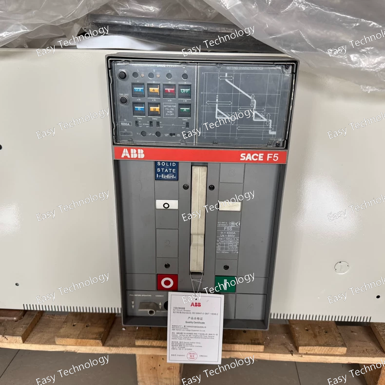
Parameter Category Specification Assembly Type High-Current LV Switchgear Functional Unit / Incomer Compartment Standard IEC 61439-1 & -2 Internal Separation Special High-Current Form (likely F5S). Expect maximum segregation, with separate compartments for busbars, breaker, and cable terminals for safety and maintenance. Busbar System • Rated Current (Ibm): 4000 A • Short-Time Withstand (Icw): Very high, typically 80 kA to 120 kA for 1s or 3s. • Peak Withstand (Ipk): ~2.2 x Icw (e.g., 176 kA to 264 kA). Main Protective Device • Type: ABB SACE Emax E4 (or large E3) Frame, Draw-out Air Circuit Breaker. • Likely Rated Current (In): 3200A, 4000A, or 5000A (matching the busbar or slightly lower). • Poles: 3 • Trip Unit: Advanced Electronic (e.g., PR122/P or PR123/P) for comprehensive protection and metering. • Breaking Capacity (Icu): Very high, matching the busbar system (e.g., 100 kA, 150 kA at 400V AC). Key Breaker Features • Heavy-Duty Draw-out Truck (W) with advanced interlocks. • High-Torque Electric Charging Motor (M). • Shunt Trip (MX) (P). Typical Additional Breaker Accessories • Full set of Auxiliary Contacts (OF/SD). • Undervoltage Release (MN). • Additional alarm and interlock contacts. • Communication module for integration into monitoring systems. Control Voltage Dedicated auxiliary supply for motor and releases (e.g., 220V DC or 230V AC). Physical Configuration Likely a wide, multi-module compartment. Includes: • Massive busbar system. • Heavy-duty draw-out breaker truck with roller mechanism. • Large cable connection chambers (front/rear). • Robust shutters and arc containment features. IP Rating (Enclosure) Typically IP31 or IP41 for indoor switchrooms.
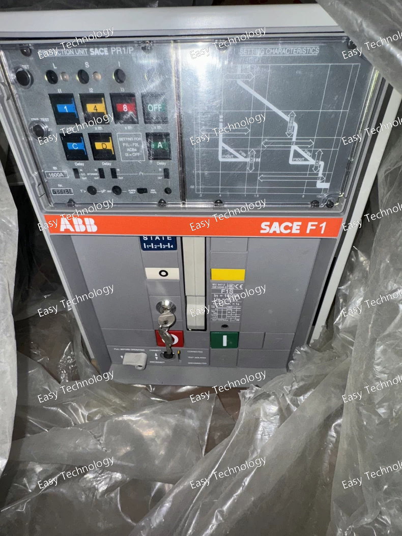
Parameter Category Specification Assembly Type LV Switchgear Functional Unit / Feeder Compartment Standard IEC 61439-1 & -2 Internal Separation Form 1 (F1) - Common compartment for busbars, breaker, and terminals. Busbar System • Rated Current (Ibm): 1600 A • Short-Time Withstand (Icw): Typically 50-65 kA for 1s (Design dependent) • Peak Withstand (Ipk): ~2.2 x Icw Main Protective Device • Type: ABB SACE Emax E1/E2 Frame, Draw-out Air Circuit Breaker. • Likely Rated Current (In): 1600A (E1.4 or E2.1 frame). Could be 1250A depending on design. • Poles: 3 • Trip Unit: Electronic (PR1 series - e.g., PR121/P). Typically provides LSI protection. • Breaking Capacity (Icu): Typically 50 kA (H) or 65 kA (N) at 400V AC, depending on specific breaker order. Key Breaker Features • Draw-out (W) for isolation, testing, and easy maintenance. • Electric Charging Motor (M) for automatic spring recharge. • Shunt Trip (MX) (P) for remote electrical tripping. Typical Additional Breaker Accessories • Auxiliary Contacts (OF/SD) for status signaling - Highly likely included but not in code; must verify. • Undervoltage Release (MN) - May or may not be included; must verify. Control Voltage Motor and shunt trip require an auxiliary control supply (e.g., 110V/220V DC or 230V AC). Must be specified separately. Physical Configuration One vertical compartment in a switchboard, including: • Draw-out breaker truck with guides and shutters. • Busbar connections. • Cable connection chamber (typically rear or bottom). • Door with possible control elements (buttons, indicators). IP Rating (Enclosure) Typically IP31, IP41, or IP54.
 TEL: Grace +86 13600179521
  Mail: info@hongkongeasy.com jilineasyyi@outlook.com
 Q Q:615739355
 ADDRESS:Unit 12, 20th Floor, Good View Commercial Centre, 2-16 Garden Street, Mong Kok, Hong Kong
 whats app


