
Industrial Controller
All product are in stock,guaranteed delivery within 3-7 days.


PRODUCT
PICTURE
BRAND
DESCRIBE
STOCK
DOWNLOAD
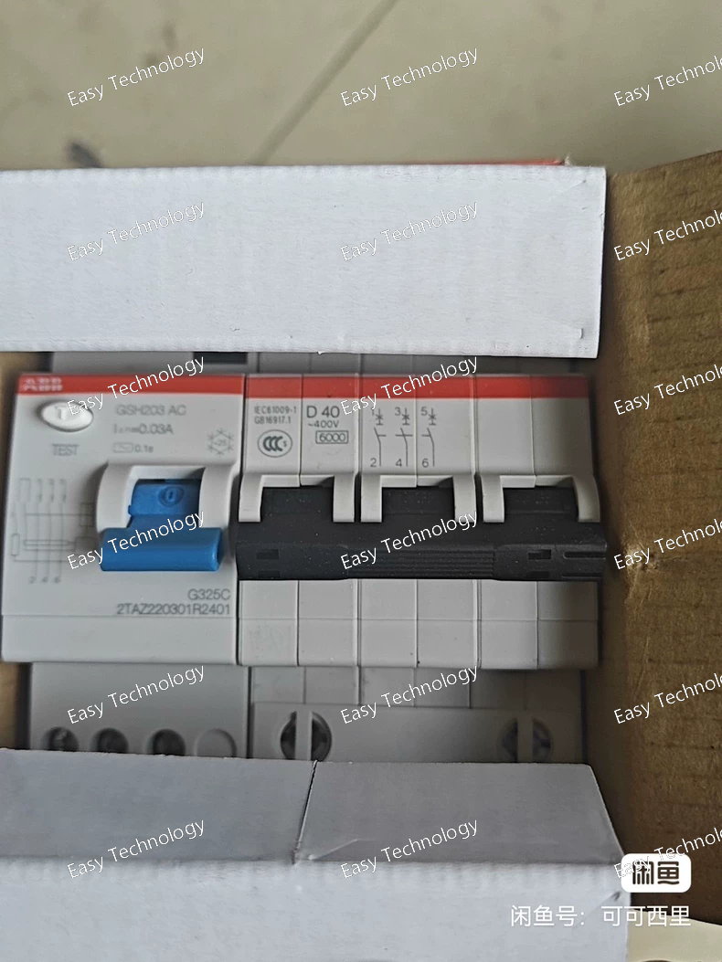
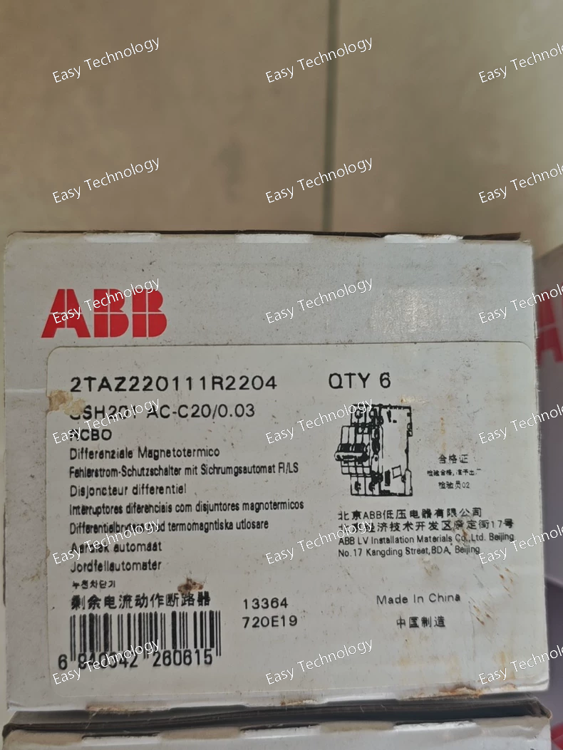
Technical Parameters Parameter Category Specification Notes Base Device GSH203 AC Frame size interpretation: GSH203 typically indicates a frame size larger than GSH202 (200A). It commonly corresponds to a 250A or 300A frame contactor within the GSH series. Main Circuit Ratings • Rated Operational Current (Ie) 250 A or 300 A (at AC-3, 400V) Exact value depends on the specific GSH203 sub-code. • Rated Operational Voltage (Ue) Up to 690 V AC Handle / Mounting Code -D40 Specific mechanical code. D often indicates a particular mounting style or accessory package. 40 is a variant code. This could denote a special side-mounted handle, a specific terminal configuration, or inclusion of certain base accessories. Critical Special Feature /0.03 Integrated 0.03A (30mA) fuse for the control coil circuit (terminals A1-A2). Control Coil Fuse (/0.03) Core Safety & Reliability Feature • Purpose To protect the external control power source (PLC output, relay, control transformer) from damage in case of a short circuit in the contactor's coil or wiring. Prevents costly damage to control electronics. • Location Housed within a dedicated compartment on the contactor assembly. • Rating 30 mA, gG or similar characteristic. • Type Standard miniature fuse (e.g., 5x20mm). Control Coil AC (type specified). Coil voltage (e.g., 230V AC) is a separate specification not shown. Must be specified separately when ordering. Utilization Categories AC-3, AC-4, AC-1 For motor and heavy resistive load switching. Switching Capacity • Making Capacity (Icm): Very high, likely 2500-4000 A (peak). • Short-circuit Withstand: Requires backup fuse/circuit breaker. Mechanical Life ≥ 10 million operations Electrical Life (AC-3) ≥ 1.0 million operations at full rated current Auxiliary Contacts Modular blocks can be added (e.g., 2NO+2NC). Mounting Foot mounting or specific mounting per -D40 code. Terminals Large screw-clamp or busbar connections.
Technical Specifications | Parameter Category | Specification / Inference | | :--- | :--- | :--- | | Product Type | High-Current Switched-Mode DC/DC Converter | | Product Family | ABB CP Series. 2TAZ is the definitive family prefix. | | Standard | IEC 62368-1, IEC 61204-7 | | Input Voltage (Uin) | Defined by 220406. This is a different input code from the previous 220301 models. This strongly suggests a different nominal input voltage. A probable interpretation is: • 2204 may correspond to a 220 V DC nominal input system (e.g., with a wide range of 180-300 V DC). • Alternatively, it could be a variant of 110V DC input. Verification from official data is critical. | | Output Voltage (Uout) | Regulated 24 V DC. The code R4504 is interpreted as follows: • R: Regulated output. • 45: Likely a high-power sub-series or product variant code. The output voltage is almost certainly the industry-standard 24V DC. • 04: Likely indicates the output current rating. In this common encoding, 04 typically corresponds to 4.0 A. However, given the 45 series code, the current could be higher (e.g., 10A, where 10 might be coded differently). A plausible and common high-power configuration is 24V/10A (240W). | | Output Current (Iout) | Likely 10.0 A (A strong possibility for a 45 series high-power module). A secondary possibility is 4.0 A (if 04 is taken literally, but this would be lower power than R2504 inferred earlier, which seems inconsistent). | | Output Power (Pout) | Estimated 240W (If 24V/10A). This is a substantially higher power module compared to the ~50W and ~100W versions previously discussed. | | Output Characteristics | • Precisely regulated voltage. • Protections: Short-circuit, overload, overvoltage, overtemperature. • Isolation: Reinforced galvanic isolation. • Low output ripple. | | Efficiency | > 88% (typical for higher-power units). | | Mounting | 35 mm DIN Rail (EN 60715), but may require more space for heat dissipation. | | Terminations | Larger screw-clamp terminals or possibly busbar connections for high-current output. | | Cooling | May incorporate a fan for forced-air cooling, given the high power density. | | Operating Temperature | -25°C to +70°C (with possible derating at high ambient temps). | | Protection Degree | IP20. | | Status Indication | Multiple LEDs (Power, Output OK, Fault). | | Safety Approvals | CE, UL, cULus. | | Typical Application | Used in large control cabinets or switchgear to power extensive 24V DC systems, such as: • Multiple protective relays and meters. • A large PLC system with numerous I/O racks. • Multiple contactors with DC coils. • Network switches, HMIs, and other ancillary electronics. |
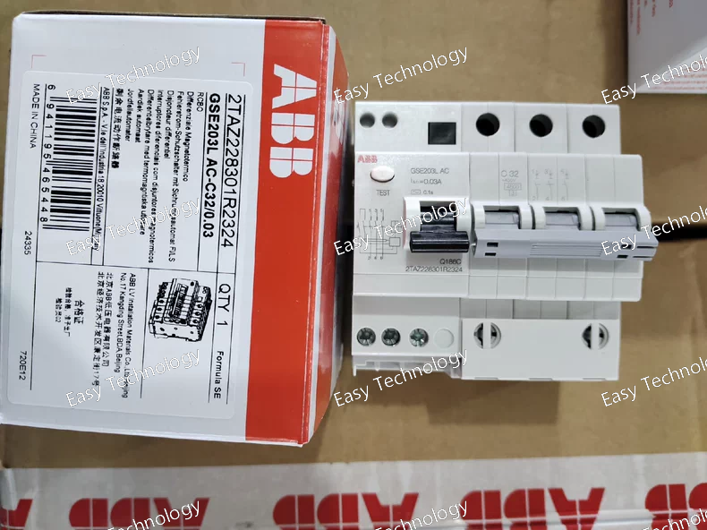
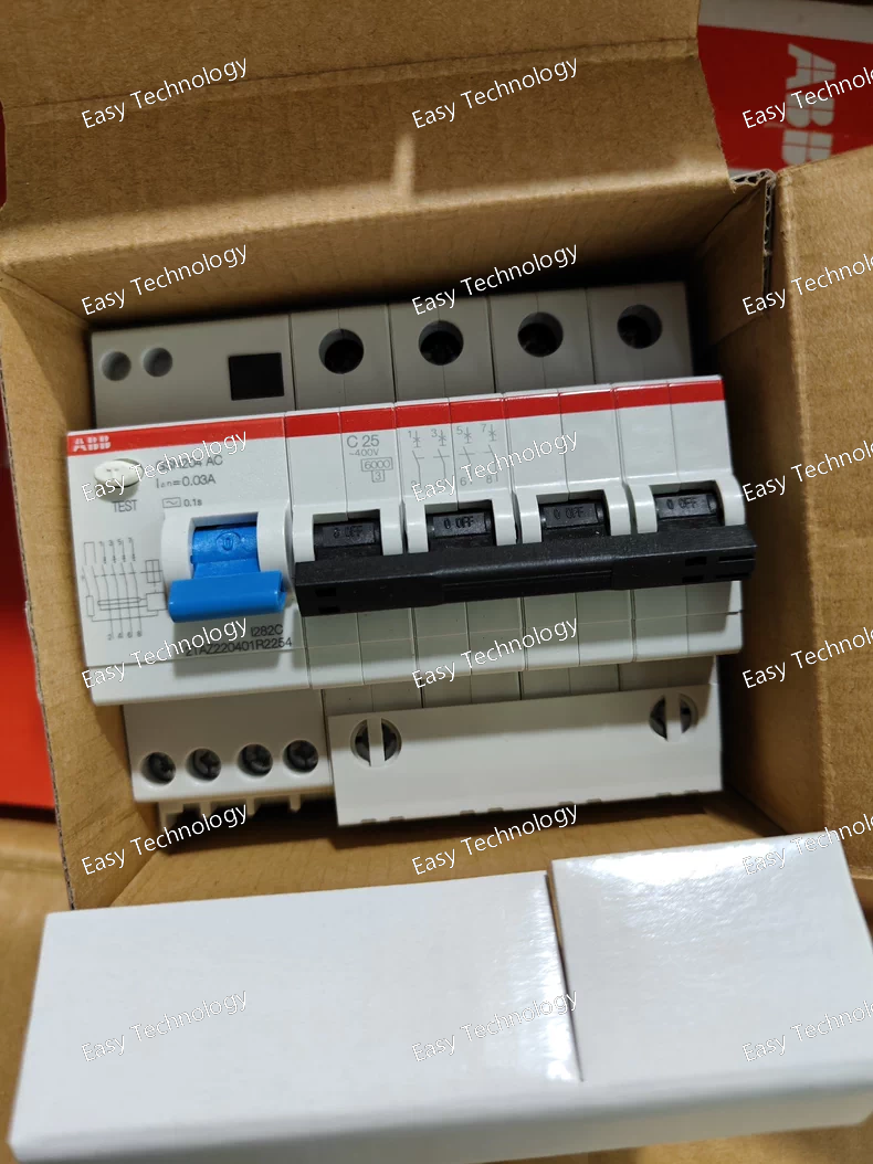
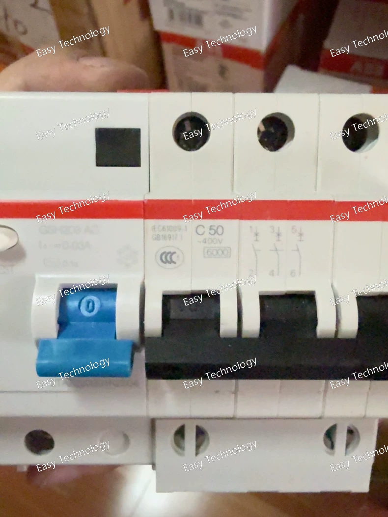
Technical Parameters Parameter Category Specification Product Series System Pro M compact - GSE Series Device Type Miniature Circuit Breaker (MCB), 3-Pole, with Special Auxiliary Protection Standard Compliance IEC/EN 60898-1 Number of Poles 3 Poles (3P) for main circuit protection. Rated Current (In) & Characteristic C32 • C: Tripping Characteristic (Instantaneous trip range: 5 to 10 times In). Suitable for general purposes with moderate inrush currents. • 32: Rated Current = 32 A per pole. Circuit Type AC ONLY (as indicated by AC). Rated Operational Voltage (Ue) 400/690 V AC Handle Type L - Side-operated rotary lever handle. Provides clear ON/OFF indication and comfortable manual operation. Special Feature /0.03 - Integrated 0.03A (30mA) protection element. • Likely Configuration: This is not a standard RCBO (residual current) trip. It is most plausibly a separate, very low-current fuse or electronic protector embedded within the MCB housing. • Protected Circuit: This likely protects a separate pair of terminals (e.g., auxiliary contacts 13-14 or a dedicated control input) used for remote signaling, undervoltage release (MN) coil, or self-powered electronic logic within the breaker. Its purpose is to prevent damage to external control devices if a fault occurs in that circuit. Breaking Capacity (Icn) Typically 6 kA or 10 kA at 400V AC for the base GSE203 model. Higher capacity versions exist (e.g., H version: 15 kA). Energy Limiting Class 3 Electrical Life ≥ 20,000 cycles at rated current Mechanical Life ≥ 20,000 cycles Terminals Screw-clamp terminals for main conductors. Additional small terminals likely for the /0.03 protected circuit. Mounting Standard 35 mm DIN Rail (EN 60715) Width 54 mm (3 module width) Ambient Temperature -25°C to +55°C Protection Degree IP20
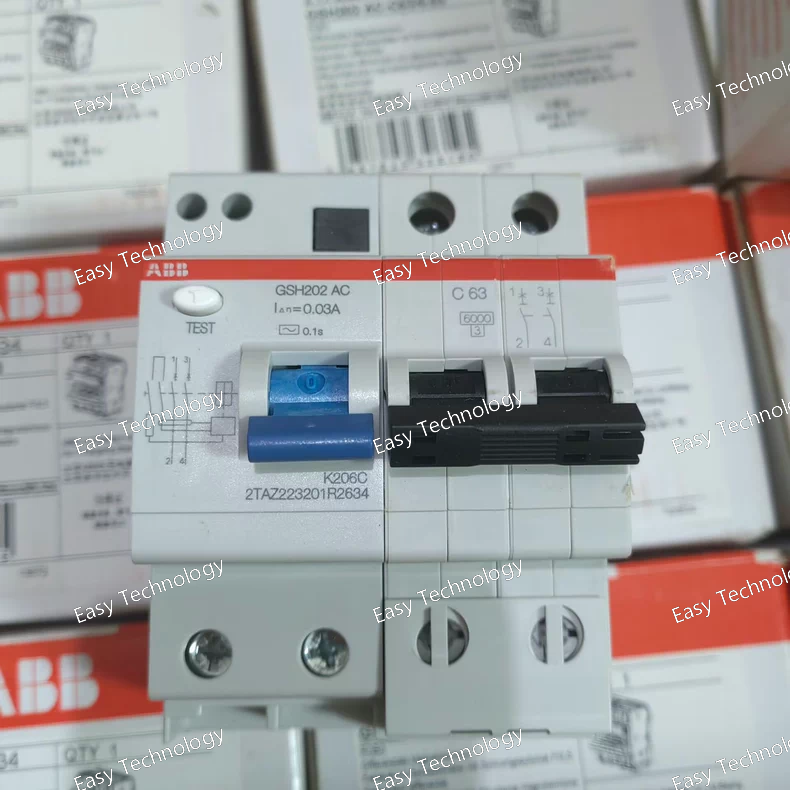
Technical Parameters Parameter Category Specification Notes Base Device GSH202 AC 200A frame high-performance contactor with AC operating coil. The specific coil voltage (e.g., 230V AC) is a separate specification not shown in this segment. Main Circuit Ratings • Rated Operational Current (Ie) 200 A (at AC-3, 400V) • Rated Operational Voltage (Ue) Up to 690 V AC Handle / Actuator -C63 Front-mounted rotary handle. The 63 is a specific code for the handle type, which likely includes features for padlocking in the OFF position and clear ON/OFF indication. Critical Special Feature /0.03 Integrated 0.03A (30mA) fuse for the control coil circuit (terminals A1-A2). Control Coil Fuse (/0.03) Core Safety Feature • Purpose To protect the external control power source from damage in case of a short circuit in the contactor's coil or its wiring. Prevents damage to PLCs, control relays, or small transformers. • Location Housed within a dedicated compartment on the contactor or its associated terminal cover. • Rating 30 mA, gG or similar characteristic. • Type Likely a standard miniature fuse (e.g., 5x20mm). Utilization Categories AC-3, AC-4, AC-1 For motor and resistive load switching. Switching Capacity • Making Capacity (Icm): ~2000 A (peak). • Short-circuit Withstand: Requires backup protection (fuse/circuit breaker). Mechanical Life ≥ 10 million operations Electrical Life (AC-3) 1-2 million operations at full rated load (200A) Auxiliary Contacts Modular blocks can be added (e.g., 2NO+2NC). Typically not included in base -C63/0.03 package. Mounting Foot mounting or DIN rail adapter.
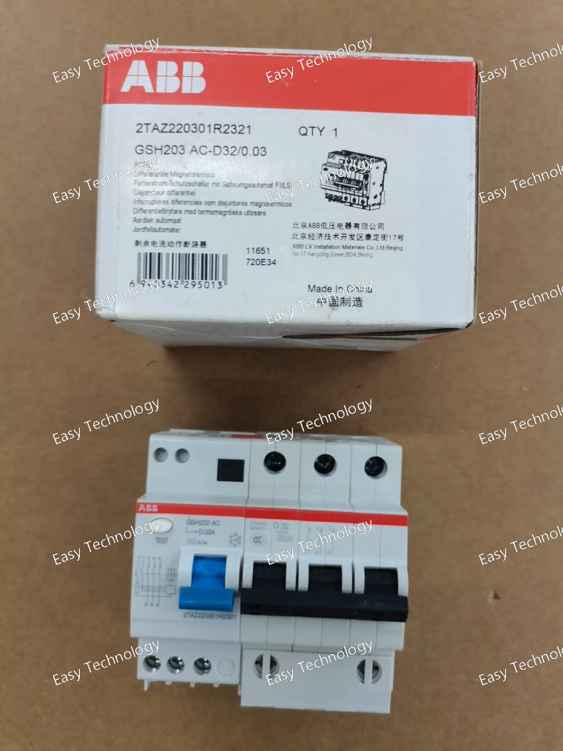
Technical Specifications | Parameter Category | Specification / Inference | | :--- | :--- | :--- | | Product Type | Switched-Mode DC/DC Converter (Single Output) | | Product Family | ABB CP-S / CP-C Series (Control Power Supplies). 2TAZ is the definitive family prefix. | | Standard | IEC 62368-1, IEC 61204-7 | | Input Voltage (Uin) | Defined by 220301. Highly likely to be 110 V DC nominal with a wide input range (e.g., 80-150 V DC). This is the most common interpretation for this code segment within this family, matching standard 110V DC control systems. Other inputs (24V, 48V, 220V DC) are possible but less likely for this specific code; verification is essential. | | Output Voltage (Uout) | Regulated 24 V DC. The code R2321 is interpreted as follows: • R: Regulated output. • 23: Likely a sub-series or product variant code. Crucially, the actual output voltage is almost certainly the industry-standard 24V DC, not 23V. • 21: Likely indicates the output current rating. In this common encoding, 21 often corresponds to 2.1 A or is coded for 2.0 A (where 2 = 2A, 1 = version). | | Output Current (Iout) | Likely 2.0 A or 2.1 A (Inferred from 21 in R2321). This is a lower current rating compared to the R2251 (5A) and R2504 (4A) variants. | | Output Power (Pout) | Approximately 48W - 50W (If output is 24V @ 2A/2.1A: 24V * 2A = 48W). | | Output Characteristics | • Precisely regulated voltage. • Protections: Short-circuit, overload, overvoltage. • Isolation: Galvanic isolation (≥ 3 kV). • Low output ripple. | | Efficiency | > 85% (typical). | | Mounting | 35 mm DIN Rail (EN 60715). | | Terminations | Screw-clamp terminals. | | Operating Temperature | -25°C to +70°C | | Cooling | Natural convection (fanless). | | Protection Degree | IP20 (for mounting inside an enclosure). | | Status Indication | LED for "Power On" / "Output OK". | | Safety Approvals | CE, UL, cULus. | | Typical Application | Used in control cabinets to power a moderate load of 24V DC devices, such as: • 1-2 mid-sized protective relays (e.g., ABB REF615). • A small PLC with a few I/O modules. • A collection of sensors and indicators. |
Technical Specifications | Parameter Category | Specification / Inference | | :--- | :--- | :--- | | Product Type | Switched-Mode DC/DC Converter (Single Output) | | Product Family | ABB CP (Control Power) or similar range. 2TAZ is the characteristic prefix. | | Standard | IEC 62368-1, IEC 61204-7 | | Input Voltage (Uin) | Defined by code segment 220301. This is the most critical parameter to verify. It is highly likely a common industrial DC voltage. Based on pattern: • A very strong possibility is 110 V DC (with a wide range, e.g., 80-150V DC). • Other possibilities: 24V DC, 48V DC, or 220V DC. Must be confirmed via datasheet or nameplate. | | Output Voltage (Uout) | Regulated 24 V DC. The code R2251 is key: • R: Regulated. • 22: Likely a sub-series or design code. The output voltage is most probably the industry-standard 24V DC, not 22V. • 51: Likely indicates the output current rating. 51 often decodes to 5A (where 5=5A, 1=version or check digit). | | Output Current (Iout) | Likely 5 A (Inferred from 51 in R2251). | | Output Power (Pout) | Approximately 120W (If output is 24V/5A: 24V * 5A = 120W). | | Output Characteristics | • Voltage regulated (±1-2%). • Short-circuit, overload, and overvoltage protected. • Galvanic isolation (typically 3-4 kV). • Low ripple and noise. | | Efficiency | > 85% (typical for this class). | | Mounting | 35 mm DIN Rail mounting. | | Terminations | Screw-clamp terminals. | | Operating Temperature | -25°C to +70°C (Industrial temperature range). | | Cooling | Natural convection (fanless). | | Protection Degree | IP20. | | Status Indication | LED power indicator. | | Safety Approvals | CE, UL, cULus. | | Typical Application | Installed in: • Low-voltage switchgear (e.g., MNS). • Motor control centers. • Automation cabinets. Function: To supply 120W of 24V DC power to devices such as: • PLCs and their I/O modules. • Protective relays (e.g., ABB REF615). • Sensors, transducers, and HMI panels. |
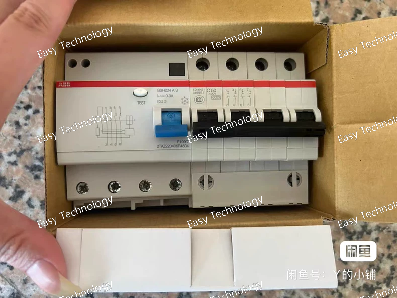
Technical Parameters Parameter Category Specification Base Device GSH204 - 400A frame high-performance contactor. The 204 denotes the 400A frame size within the GSH series. Handle & Accessory Code -C25A - This suffix defines the operating mechanism and included internal accessories. A typical decoding is: • C: Front-mounted rotary handle for manual operation. • 25: Likely a specific handle type or accessory package code. • A: Often indicates the inclusion of standard accessories. For GSH series, A commonly means the contactor is supplied with: - Auxiliary Contacts (typically 2 NO + 2 NC). - Mechanical Interlock provision or specific mounting配件. Rated Operational Current (Ie) 400 A (at AC-3, 400V). This is the key rating of the GSH204 frame. Rated Operational Voltage (Ue) Up to 690 V AC Control Coil IMPORTANT: The model GSH204 -C25A does not specify the coil voltage or type. This is a critical missing specification. The contactor requires a separate coil, ordered with a code like GSH204 A230 for a 230V AC coil, which is then combined with the -C25A handle/accessory code. Utilization Categories AC-3 (For squirrel-cage motors: Starting, switching off during running) AC-4 (For squirrel-cage motors: Starting, plugging, inching - at a significantly reduced current rating) AC-1 (Non-inductive loads) Switching Capacity • Rated Making Capacity (Icm): Very high, typically several thousand Amperes (e.g., 4000A peak) to handle motor inrush. • Short-circuit Withstand: Requires backup fuse/circuit breaker for short-circuit protection. Mechanical Life ≥ 10 million operations Electrical Life (AC-3) ≥ 1.0 million operations at full rated current (400A) Auxiliary Contacts (if A includes them) Typically 2 changeover (NO+NC) contacts, rated for control circuits (e.g., 10A, 600V AC). Terminals Large screw-clamp terminals or busbar connections for high-current cables. Mounting Robust foot mounting for panel installation. May require a sturdy backplate. Dimensions & Weight Substantial. Approx. width > 200mm, weight > 10kg.
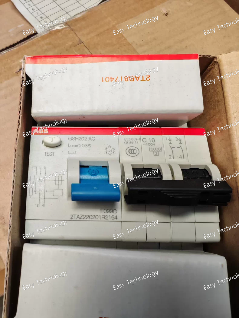
Technical Parameters Parameter Category Specification Base Device GSH202 AC - 200A frame high-performance contactor with AC operating coil. Note: The specific coil voltage (e.g., 230V AC) is part of the ordering code but not shown in this segment. Main Circuit Ratings • Rated Operational Current (Ie) 200 A (at AC-3, 400V) • Rated Operational Voltage (Ue) Up to 690 V AC Handle / Actuator -C16 - Front-mounted rotary handle for local manual operation, testing, and padlocking in the OFF position. Critical Special Feature /0.03 - Integrated 0.03A (30mA) fuse for the control coil circuit. Control Coil Fuse (/0.03) • Purpose To protect the external control power source (e.g., PLC digital output, safety relay, control transformer) from damage in the event of a short circuit in the contactor's coil (A1-A2) or its connecting wires. • Location Housed within a dedicated compartment on the contactor or its associated terminal cover. • Rating 30 mA, gG or similar characteristic. • Replacement Typically a standard 5x20mm or similar miniature fuse. Utilization Categories AC-3, AC-4, AC-1 Switching Capacity Icm: ~2000A; Icu: 15-20 kA (with appropriate backup protection) Mechanical Life ≥ 10 million operations Electrical Life (AC-3) 1-2 million operations at full load Auxiliary Contacts Modular blocks can be added (e.g., 2NO+2NC). Mounting Foot mounting or DIN rail adapter.
Parameter Category Specification / Inference Product Type Switched-Mode DC/DC Converter (Power Supply Module) Product Family ABB CP-S (Control Power) or similar range. 2TAZ is a common prefix for this family. Standard IEC 62368-1, IEC 61204-7 Input Voltage (Uin) Wide-range DC input. The code segment 220301 defines the exact range. A highly probable and common input is 110-150 V DC (compatible with standard 110V DC control systems). Other possibilities include 24V, 48V, or 220V DC. This must be verified from the datasheet. Output Voltage (Uout) Regulated 24 V DC. This is strongly indicated by the R24 portion of the code R2504. The R stands for "Regulated". (Note: R25 is unusual; it might be a specific series code, but the output is highly likely 24V DC for industrial control). Output Current (Iout) / Power (Pout) The 04 in R2504 typically indicates the output current rating. Likely 4 A at the rated output voltage. • If output is 24V DC: Power = 24V * 4A = 96W. • If output is another voltage: Power scales accordingly. Output Power (Typical) Approximately 100W (e.g., 24V/4A or 48V/2A). Output Characteristics • Voltage regulated. • Short-circuit and overload protected. • Electrical isolation between input and output (typically 3-4 kV). • Low output ripple. Efficiency Typically >85%. Mounting 35 mm DIN Rail mounting. Terminations Screw-clamp terminals for secure connection. Operating Temperature -25°C to +70°C (industrial grade). Storage Temperature -40°C to +85°C. Protection Degree IP20 (for installation inside an enclosure). Cooling Convection cooled (no fan). Status Indication LED for power/operation status. Safety Approvals CE, UL, cUL, etc. Typical Application Installed in: • Low-voltage switchgear (MNS, ArTu). • Motor control centers (MCCs). • Automation panels. Function: To supply power to 24V DC devices (PLCs, I/O cards, relays, indicators) from a 110V DC or other primary DC bus.
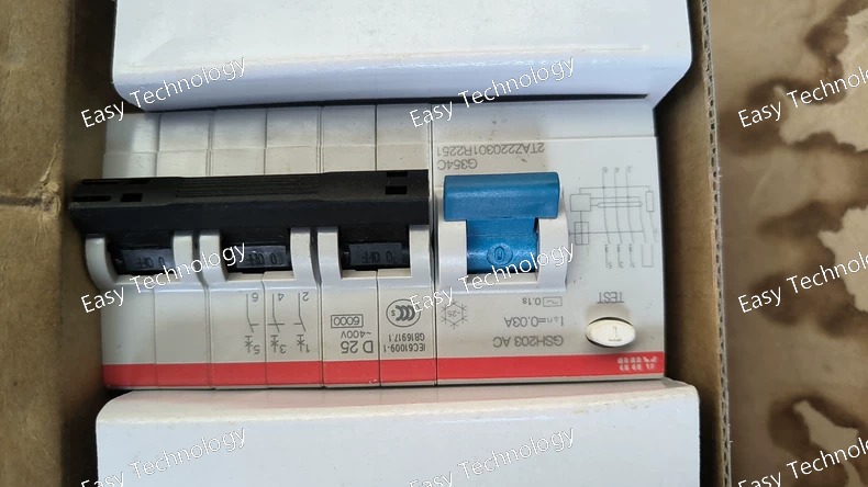
Technical Specifications Parameter Category Specification Product Series System Pro M compact - GSE Series Device Type Miniature Circuit Breaker (MCB), 3-Pole Standard Compliance IEC/EN 60898-1 (Primary standard for household and similar installations). May also comply with parts of IEC/EN 60947-2 for industrial applications. Number of Poles 3 Poles (3P). All three poles are identically protected. Rated Current (In) This is NOT defined by the "203" code alone. The 203 indicates a 3-pole frame. The rated current must be specified separately as a suffix. Common ratings for this frame: 1A, 2A, 4A, 6A, 10A, 13A, 16A, 20A, 25A, 32A, 40A. A complete model would be, for example: GSE203 C32 AC (3-Pole, C-curve, 32A). Tripping Characteristic Not specified in "GSE203 AC". Must be selected from: • B Characteristic: (3 to 5 x In) • C Characteristic: (5 to 10 x In) - Most common for general three-phase loads. • D Characteristic: (10 to 20 x In) - For loads with very high inrush currents. Circuit Type AC ONLY (as indicated by the AC suffix). Not suitable for DC circuits. Rated Operational Voltage (Ue) 400/690 V AC (Phase-to-Phase) Rated Insulation Voltage (Ui) 500 V AC Rated Impulse Withstand Voltage (Uimp) 6 kV (For overvoltage category III) Breaking Capacity (Icn) Depends on the specific version. Common ratings for the GSE203 base model: • Standard: 6 kA or 10 kA at 400V AC • High Performance (H version): 15 kA Energy Limiting Class 3 (High) Electrical Life ≥ 20,000 cycles at rated current Mechanical Life ≥ 20,000 cycles Handle Type Standard toggle (rocker) handle with clear ON/OFF indication. Terminals • Screw-clamp terminals suitable for rigid and flexible conductors. • Connection Capacity: Up to 35 mm² (depending on wire type). Mounting Standard 35 mm DIN Rail (EN 60715) Width 54 mm (3 module width = 3 x 18mm) Dimensions (W x H x D) 54 mm x 89 mm x 69 mm Ambient Temperature -25°C to +55°C (Reference calibration at 30°C) Protection Degree IP20 (When mounted in an enclosure) Certifications CE, CCC, and other international approvals.
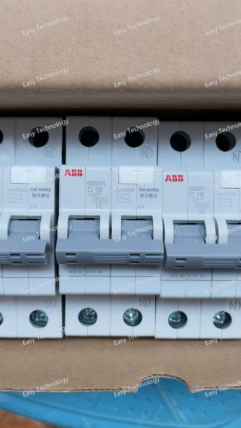
Technical Specifications Parameter Category Specification Product Series System Pro M compact - GSE Series Device Type Miniature Circuit Breaker (MCB), 1P+N Type Standard Compliance IEC/EN 60898-1 (and possibly IEC/EN 60947-2 for industrial use) Number of Poles & Protected Poles 1 Pole + Neutral (1P+N). Both poles are switched, but only the phase pole contains the full thermal-magnetic tripping mechanism for overload and short-circuit protection. The neutral pole typically provides isolation and short-circuit breaking capability. Rated Current (In) 16 A Tripping Characteristic Not specified in the basic model. Must be selected from common options: • B Characteristic: (3 to 5 x In) For residential/sensitive applications. • C Characteristic: (5 to 10 x In) Most common for general purpose. • D Characteristic: (10 to 20 x In) For high inrush currents. Rated Operational Voltage (Ue) 230/400 V AC Rated Insulation Voltage (Ui) 500 V AC Rated Impulse Withstand Voltage (Uimp) 4 kV Breaking Capacity (Icn) Typically 6 kA at 230/400V AC for the base GSE201 model. Higher versions (e.g., GSE201H) offer 10 kA. Energy Limiting Class 3 Electrical Life ≥ 20,000 cycles at rated current Mechanical Life ≥ 20,000 cycles Handle Type (L) Side-operated rotary lever. Provides clear ON (I)/OFF (0) indication and comfortable manual operation. Terminals • Screw-clamp terminals suitable for both rigid and flexible conductors. • Connection Capacity: 1 x 25 mm² or 2 x 1.5 - 16 mm² (with ferrule). Mounting Standard 35 mm DIN Rail (EN 60715) Ambient Temperature -25°C to +55°C (Reference calibration at 30°C) Protection Degree IP20 (When mounted in an enclosure) Width 18 mm (1 module width) – A key advantage of the GSE series for 1P+N breakers. Dimensions (W x H x D) 18 mm x 89 mm x 69 mm Weight ~ 0.12 kg Certifications CE, CCC, and other international approvals.
Technical Parameters Parameter Category Specification Notes / Explanation Base Device GSH201 AC 100A frame high-performance contactor, AC coil. Coil voltage (e.g., 230V AC) is a separate specification. Main Circuit Ratings • Rated Operational Current (Ie) 100 A (at AC-3, 400V) • Rated Operational Voltage (Ue) Up to 690 V AC Handle / Actuator -C20 Front-mounted rotary handle for local manual operation, with ON/OFF indication and padlocking capability in the OFF position. Critical Special Specification /0.03 Integrated 0.03A (30mA) fuse for the control coil circuit (terminals A1-A2). This protects the control power source (e.g., PLC output, transformer) from damage in case of an internal coil short circuit. Control Coil Fuse (/0.03) Unique Safety Feature • Protected Circuit The contactor's AC control coil circuit. • Fuse Rating 0.03 A (30 mA) gG or similar. • Purpose To provide precise overcurrent protection for the sensitive control circuit. • Location Housed within a dedicated compartment on the contactor assembly. Typical Accessories Modular auxiliary contact blocks can be added. Mounting Foot mounting or DIN rail adapter.
 TEL: Grace +86 13600179521
  Mail: info@hongkongeasy.com jilineasyyi@outlook.com
 Q Q:615739355
 ADDRESS:Unit 12, 20th Floor, Good View Commercial Centre, 2-16 Garden Street, Mong Kok, Hong Kong
 whats app


