
Industrial Controller
All product are in stock,guaranteed delivery within 3-7 days.


PRODUCT
PICTURE
BRAND
DESCRIBE
STOCK
DOWNLOAD
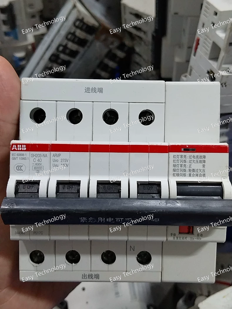
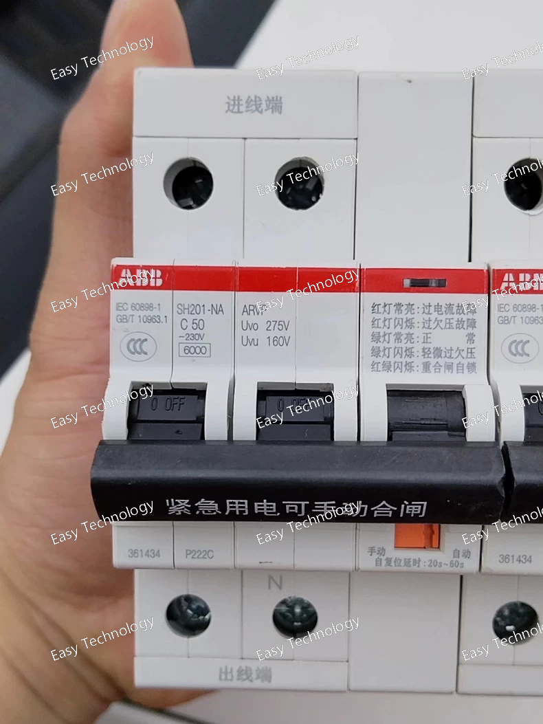
Technical Specifications / Parameters Parameter Specification Manufacturer Type Code SH203-NA ARVP Brand / Series ABB System PRO M compact® (Modified/Variant with Accessory) Device Type Miniature Circuit Breaker (MCB) with Integrated Auxiliary Contact Number of Poles 3-Pole (3P) Rated Current (In) Not specified in code; must be selected (e.g., 16A, 20A, 25A, 32A, etc.). The "SH203" base supports a range. Rated Operational Voltage (Ue) 400V AC (3-phase) Tripping Characteristic Not explicitly stated. Typically C Curve for general three-phase loads (motors, heaters, distribution), but must be verified. Rated Breaking Capacity (Icn) HIGH. The "-NA" suffix strongly indicates a High Breaking Capacity (HBC) version, likely 10 kA or 15 kA, exceeding the standard 6kA of the base SH series. Auxiliary Function (ARVP) Integrated Auxiliary Switch/Alarm Contact. • "ARVP" is a specific ABB accessory code. It commonly refers to a single-pole, changeover (SPDT) auxiliary contact with a specific switching logic (e.g., "trip-indicating" or "remote signaling"). • Function: Provides a dry contact (NO/NC) that changes state based on the breaker's position (ON/OFF) or trip status. Used for remote indication, PLC interlocking, or alarm circuits. Auxiliary Contact Rating Typically low-current signal rating (e.g., 6A / 250V AC). Standards Compliance IEC/EN 60898-1, and likely additional certifications for the accessory. Terminal Type Cage Clamp Terminal for main poles and auxiliary wires. Mounting DIN Rail Mounting (35mm rail). Module Width 54 mm (3 Poles) + additional width for the integrated accessory module. Primary Functions Overload Protection, Short-Circuit Protection, Remote Status Signaling.
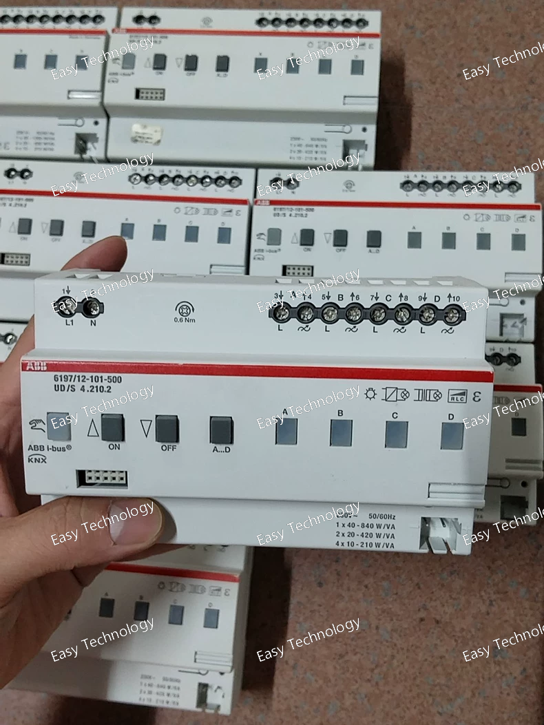
Technical Specifications / Parameters Parameter Specification Manufacturer Order Code 6197/12-101-500 UD/S 4.210.2 Product Family / Series ABB UD Series (Electronic Transducers / Signal Conditioners) Device Type Single-Phase AC Voltage Transducer (Isolating Converter) Primary Function To convert an AC voltage input into an isolated, proportional DC current or voltage output. Input (Measured Variable) AC Voltage Rated Input Voltage (Vn) 500 V AC (Likely the nominal or maximum input range, e.g., 0-500V AC). Input Frequency Typically 50/60 Hz. Output Signal Standard Analog Output, definitively specified by the suffix 4.210.2. Interpretation (Common Code): • 4.2 often indicates a 4-20 mA DC two-wire output. • 10.2 likely defines the input-to-output scaling. A common mapping for this code is: 0-500V AC input corresponds to 0-20mA (or 4-20mA) output. 必须查阅手册确认。 Power Supply For a 4-20mA two-wire model: Loop powered by the receiving device (e.g., PLC AI card). The supply voltage range is typically 16...30 V DC across the loop. Accuracy High accuracy, typically ±0.2% of full scale. Isolation Galvanic isolation between input, output, and power circuits. Test voltage typically 2-4 kV AC. Mounting DIN Rail Mounting (35mm). Connection Screw-clamp terminals. Operating Temperature Typically -20°C to +70°C. Response Time < 250 ms. Burden / Load Resistance For current output: Maximum loop resistance (e.g., 500 Ω at 24V). Standards & Approvals IEC/EN 61010-1 (Safety), IEC/EN 61326 (EMC), CE. Typical Applications • Main voltage monitoring in LV switchgear and MCCs. • Generator output voltage measurement for control or synchronization. • Busbar voltage feedback to Automatic Voltage Regulators (AVRs). • Energy management and power quality monitoring systems. • Any process requiring a safe, accurate, and isolated representation of an AC voltage.
Technical Specifications / Parameters Parameter Specification Manufacturer Order Code 2TAM200000R1410 Product Family ABB Push Button & Indicator Light System (Mechanical Accessories) Device Type Mounting Frame / Assembly Bracket Kit Primary Function To provide a rigid mounting structure for grouping and installing multiple 22.5mm operator devices (pushbuttons, switches, indicators) from the front of a panel. Compatible Devices ABB operator modules with 22.5mm mounting diameter (e.g., from the CP-S, CPX, or similar series). Mounting Method The bracket is designed to be secured behind the panel using screws or bolts. Individual operator modules then snap into the bracket from the front of the panel, allowing for easy installation and replacement without tools. Material Typically made of sturdy, corrosion-resistant zinc-plated steel or aluminum. Capacity (Number of Modules) The specific kit 2TAM200000R1410 is typically configured for a common arrangement, such as a single-row frame holding 4 modules. This must be verified with the catalog. Included Components The kit usually contains: • 1 x Main Mounting Frame • Required mounting screws/nuts • Possible end plates or blanks to fill unused positions and maintain IP rating. Panel Thickness Range Designed to accommodate a standard range of panel thicknesses (e.g., 1mm to 4mm). Sealing When used with compatible sealing rings/gaskets on the operator modules and optional end plates, the assembled block can achieve a high degree of front-panel protection (up to IP65/IP66). Installation The panel must be drilled with precise 22.5mm diameter holes on a standardized center-to-center spacing (e.g., 30mm or 36mm) to match the bracket. Typical Applications • Building control stations on industrial machinery. • Custom operator panels for process control. • Any application requiring a clean, robust, and modular arrangement of multiple control devices.
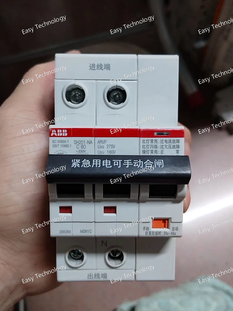
Technical Specifications / Parameters Parameter Specification Manufacturer Type Code SH201-NA 2P 80A (Note: The "NA" suffix is critical and typically denotes a special variant.) Brand / Series ABB System PRO M compact® (Modified/Variant) Device Type Miniature Circuit Breaker (MCB) - Special High-Capacity or Specific Application Type Number of Poles 2-Pole (2P) Rated Current (In) 80 A Rated Operational Voltage (Ue) 230/400V AC Rated Insulation Voltage (Ui) 500V AC Tripping Characteristic Not explicitly stated. Typically follows the standard curve for this current rating, most likely C Curve for general applications, but must be verified. Rated Breaking Capacity (Icn) Expected to be HIGHER than standard SH201 breakers (6kA). The "NA" suffix often indicates a High Breaking Capacity (HBC) version, potentially 10 kA or 15 kA. This is the key distinction of this model. Standards Compliance IEC/EN 60898-1 and likely additional certifications for the higher breaking capacity. Terminal Type Cage Clamp Terminal (likely designed for larger conductors). Connectable Conductors 35 mm² (Typical maximum for this current rating). Mechanical Life ≥ 20,000 operations Electrical Life ≥ 20,000 operations (at In) Mounting DIN Rail Mounting (35mm symmetrical rail, EN 60715) Module Width 36 mm (2 Poles) Primary Functions Overload Protection, Short-Circuit Protection.
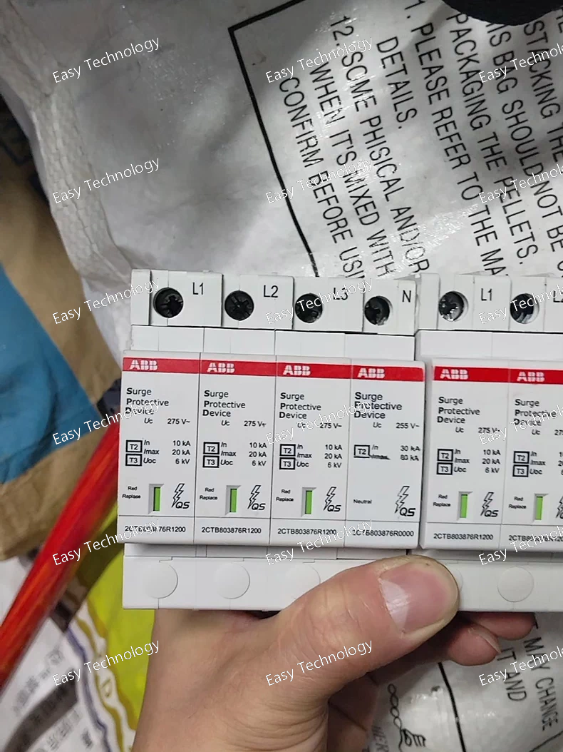
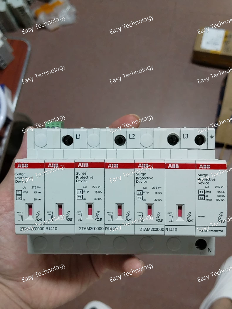
Technical Specifications / Parameters Parameter Specification Manufacturer Type Code OVR T2-T3 3N 20-275 P QS Brand / Series ABB OVR Series (Surge Protection Devices) Device Type Type 2 Surge Protective Device (SPD) Application Main distribution board or sub-distribution board protection (according to IEC 62305). Rated Voltage (Uc) 275 V AC (for 230/400V AC systems). This is the maximum continuous operating voltage. Network Configuration 3N (Three-phase + Neutral protection). It protects all phases (L1, L2, L3) relative to Neutral (N). Nominal Discharge Current (In) 20 kA (8/20 µs) per phase. This is the standard test current for Type 2 SPDs. Maximum Discharge Current (Imax) Significantly higher than In (e.g., 40 kA or 65 kA 8/20 µs). Voltage Protection Level (Up) Low (e.g., ≤ 1.5 kV). This is the residual voltage that appears across the terminals when discharging In, indicating its clamping performance. Protection Mode L-N, N-PE (Depending on design, it may protect between each Line and Neutral, and Neutral to Earth). Short-Circuit Withstand Rating High (e.g., 25 kA RMS according to IEC 61643-11). Thermal Protection Integrated thermal disconnector for safe failure mode. Status Indicator Green/Red window indicating operational health (Green = OK, Red = fault/end of life). Remote Signaling Contact (QS) Yes. The QS suffix indicates a built-in Changeover (SPDT) auxiliary contact for remote alarm signaling (e.g., to a BMS or PLC). Mounting DIN Rail Mounting (35mm). Standards & Approvals IEC/EN 61643-11, UL 1449 (4th Ed.) Type 2, CE.
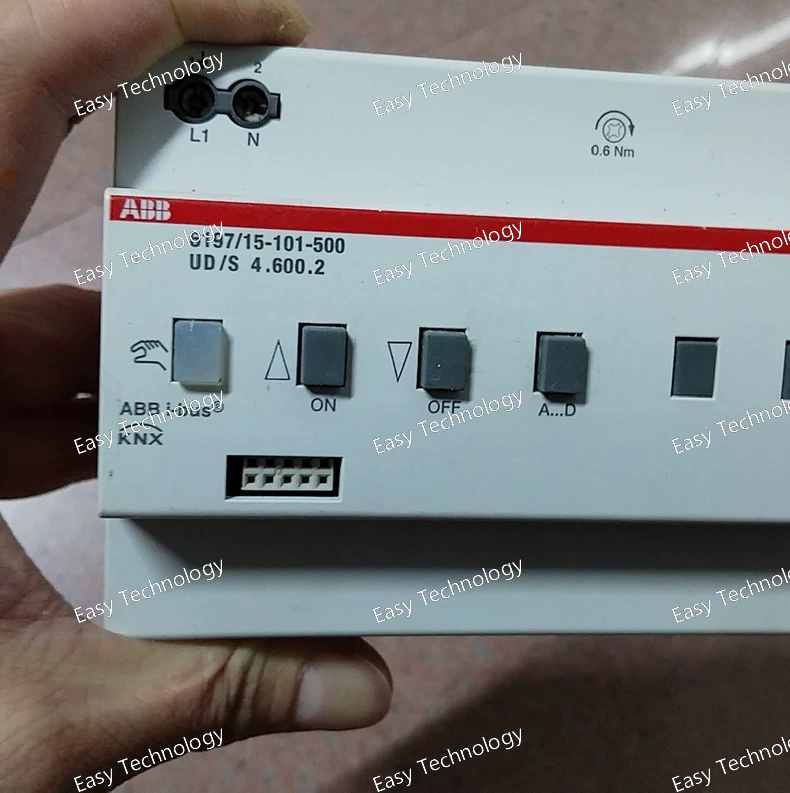
Technical Specifications / Parameters Parameter Specification Manufacturer Type Code 6197/15-101-500 UD/S 4.600.2 Product Family / Series ABB Instrumentation / Transducers (UD Series or similar) Device Type Electronic Voltage Transducer / Signal Converter / Isolator Primary Function To provide galvanic isolation and conversion of an AC voltage input to a proportional DC analog output signal. Input (Measured Variable) AC Voltage Input Voltage Range (Nominal) 500V AC (Likely the nominal or maximum input voltage, e.g., 0-500V AC). Input Frequency Typically 50/60 Hz. Output Signal Standard Analog Output, most commonly: • 4...20 mA DC (two-wire loop powered) 或 • 0...10 V DC (three-wire, with separate supply). (The suffix 4.600.2 often indicates a specific output type and scaling.) Power Supply Depends on output type: • For 4-20mA two-wire: Loop powered (16-30V DC typically). • For 0-10V three-wire: Requires external auxiliary supply (e.g., 24V DC, 110/230V AC). Accuracy High accuracy, typically ±0.2% or better of full scale. Isolation Galvanic isolation between input, output, and power supply circuits (typically 2-4 kV). This protects connected equipment from transients and ground loops. Mounting DIN Rail Mounting (35mm). Connection Screw-clamp terminals. Operating Temperature Typically -20°C to +70°C. Response Time < 250 ms. Standards & Approvals IEC/EN 61010-1 (Safety), IEC/EN 61326 (EMC), CE, UL, cUL. Typical Applications • Main voltage monitoring in switchgear and control panels. • Generator output voltage measurement. • Busbar voltage feedback for automatic voltage regulators (AVRs). • Power quality monitoring systems. • Any process requiring a safe, accurate, and isolated representation of an AC voltage for control or logging.
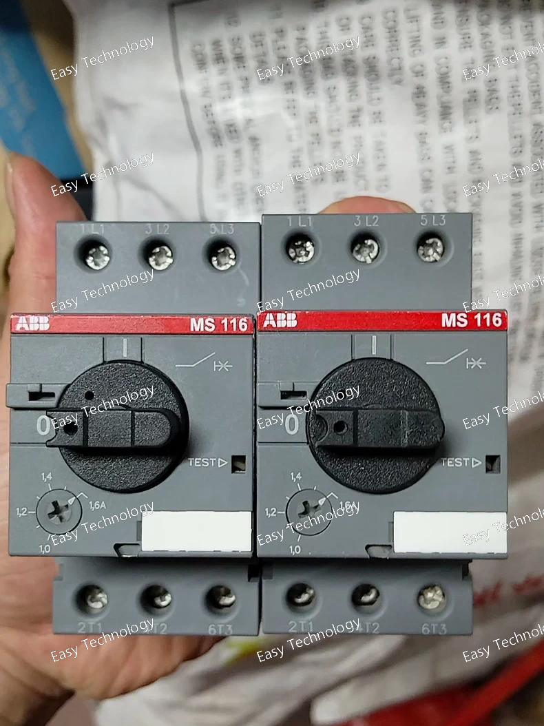
Technical Specifications / Parameters Parameter Specification Manufacturer Type Code MS116-1.6 Brand / Series ABB MS (Motor Starter) Series - Thermal Overload Relay (TOL) Device Type Thermal Overload Relay (Direct Heating, Bi-metallic) Protection Functions • Sustained Overload Protection (Inverse Time Characteristic) • Single-Phase (Phase Loss) Protection (through inherent design imbalance) • Motor Locked Rotor Protection Rated Operational Current (Ie) The device's operational range. For MS116-1.6, the setting range is 1.0 to 1.6 A. Setting Current (Ir) Adjustable via a dial within the specified range (1.0 - 1.6 A). This should be set to the motor's full-load current (FLC) as stated on its nameplate. Ambient Temperature Compensation Yes (Built-in). The bimetal system compensates for variations in the surrounding air temperature, ensuring accurate protection. Trip Class Typically Class 10 (Standard trip time at 7.2 x Ir is about 10 seconds). This is suitable for standard motor starting. Control Contacts • 1 Normally Closed (NC) Contact (95-96): Used to break the contactor coil circuit upon trip. • 1 Normally Open (NO) Contact (97-98): Can be used for a trip indication/alarm circuit. Contact Ratings Typically: • NC (95-96): 6A / 230V AC (AC-15) • NO (97-98): 6A / 230V AC (AC-15) Mounting Direct Snap-on mounting onto compatible ABB contactors (e.g., A-series) or onto a separate mounting base. Reset Mode Manual reset (push-button) after a trip and cool-down period. Automatic reset versions are available as separate variants. Standards Compliance IEC/EN 60947-4-1, UL 508, CSA C22.2 No. 14. Application Protection of small three-phase motors with full-load currents between 1.0 and 1.6 Amperes.
Technical Specifications / Parameters Parameter Specification Manufacturer Type Code 2P40A50A63A Brand ABB Product Line Typically from the System PRO M compact® (SH/S200 Series) or similar ABB MCB range. Device Type Miniature Circuit Breaker (MCB) Number of Poles 2-Pole (2P) Rated Current (In) 40 A Rated Operational Voltage (Ue) 230/400V AC Rated Insulation Voltage (Ui) 500V AC Tripping Characteristic A Curve (Very fast magnetic response. Instantaneous tripping range: 2In to 3In). Rated Breaking Capacity (Icn) Typically 6 kA or 10 kA, depending on series (e.g., SH series: 6kA, S200 series: 10kA). Standards Compliance IEC/EN 60898-1 (Primary standard for household and similar installations). Terminal Type Cage Clamp Terminal Connectable Conductors Rigid/Flexible Copper: 1 - 35 mm² (typical for this current rating) Mechanical Life ≥ 20,000 operations Electrical Life ≥ 20,000 operations (at In) Mounting DIN Rail Mounting (35mm symmetrical rail, EN 60715) Module Width 36 mm (2 Poles) Primary Functions Overload (Thermal) Protection, Very Fast Short-Circuit Protection
Technical Specifications / Parameters Parameter Specification Manufacturer Order Code 1SVR040010R0000 Catalogue Type CC-U/STDR Brand / Series ABB CR-U Series (Universal Monitoring Relays) Device Type Universal Resistance Monitoring Relay Monitoring Function Monitors the ohmic resistance (R) of a two-wire loop connected to its input terminals. Measurement Principle Applies a constant DC measuring current and measures the resulting voltage drop to calculate resistance. Resistance Measurement Range Typically from a few ohms (Ω) up to several megaohms (MΩ). Specific ranges (e.g., 0-10kΩ, 0-1MΩ) are selectable via front switches or DIPs. 必须核实具体型号范围。 Number of Setpoints Two independent adjustable setpoints (High and Low), typically via potentiometers. Setpoint Logic Configurable to trigger when resistance is above a high limit, below a low limit, or inside/outside a window defined by the two limits. Output Relay 1 Changeover (CO) Contact (SPDT: 1 NO + 1 NC) • Contact Rating: Typically 6A / 250V AC (resistive load). Power Supply (Auxiliary) 24...240V AC/DC (wide-range, for relay electronics). Measuring Voltage/Current Uses a low, safe DC voltage/current for measurement to avoid influencing the monitored system (e.g., < 10V DC). Status Indication LEDs for Power, Alarm/Trip, and sometimes Measurement Active. Hysteresis Adjustable or fixed, to prevent output chatter near the setpoint. Mounting DIN Rail Mounting (35mm). Module Width 22.5 mm (1 module width). Operating Temperature -25°C to +55°C. Front Protection Degree IP40. Standards & Approvals IEC/EN 60255, UL 508, CSA C22.2 No. 14, CE, cULus. Typical Applications • Conductivity-based liquid level detection in tanks (probe resistance changes when immersed). • Moisture or humidity detection (with resistive humidity sensors). • Monitoring of heating elements for open circuit (infinite resistance) or degradation. • Ground electrode or bonding strap continuity checking. • Simple insulation monitoring of low-voltage circuits (e.g., detecting coolant leakage into a motor winding).
Technical Specifications / Parameters Parameter Specification Manufacturer Order Code 1SVR040008R1300 Product Family / Series ABB CR-M / CM-MSN.x Series (Current Monitoring Relays) Device Type Universal Current Monitoring Relay Monitoring Functions • Overcurrent (I>) • Undercurrent (I<) • Phase Failure Detection (when used in 3-phase mode with multiple relays or a specific variant) Current Input • Direct Input: Typically up to 5A AC via internal measurement circuit. • External CT Input: For higher currents, connects to standard 1A or 5A secondary current transformers. Setting Range (via DIP) Adjustable over a wide range (e.g., from 10% to 200% of the CT secondary current), selectable via DIP switches. Power Supply (Us) Wide-range 24...240V AC/DC (auto-sensing). Output Relay 1 Changeover (CO) Contact (SPDT: 1 NO + 1 NC) • Contact Rating: Typically 6A / 250V AC (resistive load). Setpoint Adjustment Via rotary DIP switches on the front/side for selecting current range and trip threshold (as a percentage of the set nominal current). Time Delays Adjustable start-up delay (to ignore inrush currents) and trip delay (for stable operation). Status Indication LEDs for Power (ON), Alarm/Trip, and sometimes Load Current Present. Mounting DIN Rail Mounting (35mm). Module Width 22.5mm (1 module width) or 17.5mm (for ultra-compact variants). Operating Temperature -25°C ... +55°C. Standards & Approvals IEC/EN 60255, UL 508, CSA C22.2 No. 14, CE, cULus listed. Connection Screw-clamp terminals. Typical Applications • Motor protection against overload, underload (e.g., pump dry-run), and phase loss. • Heating element monitoring for broken filaments. • Fan and blower supervision (detecting belt slippage or blockage via undercurrent). • Pump sequencing and duty control. • General machine monitoring for tool breakage or jamming.
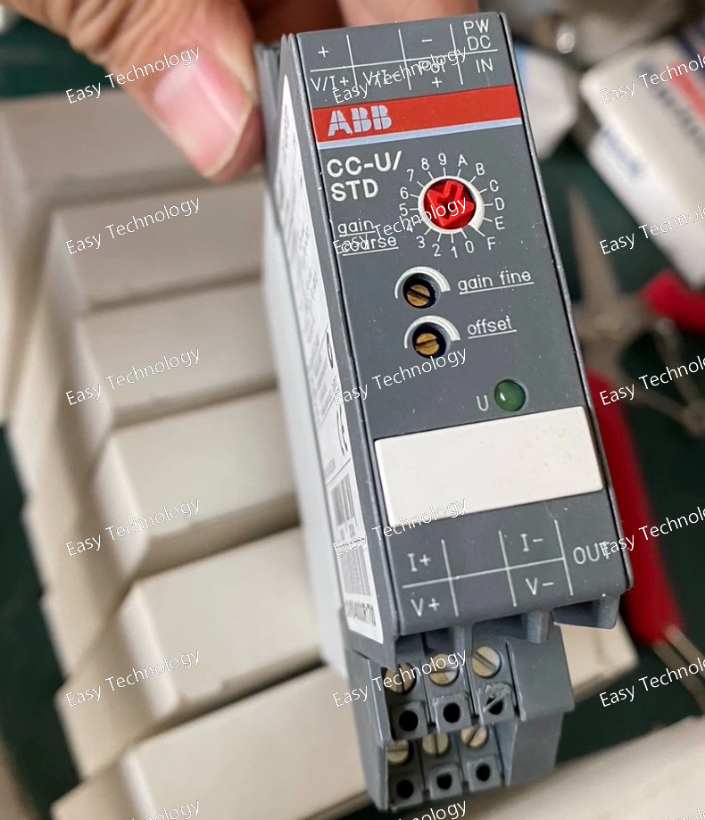
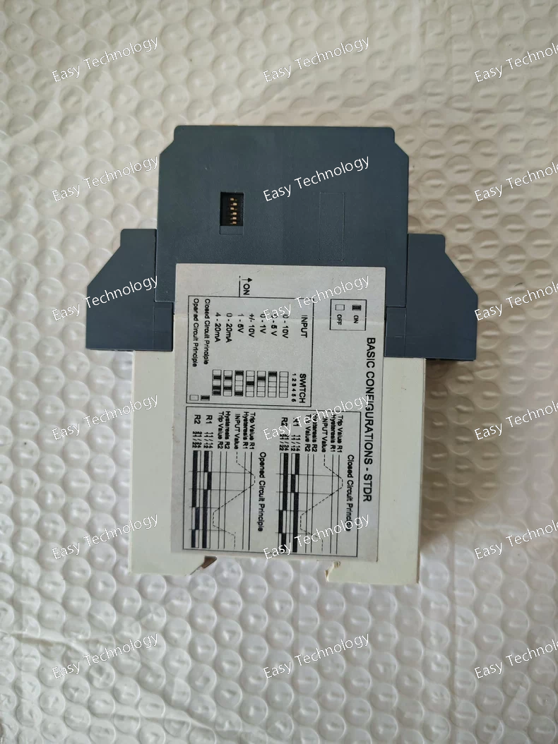
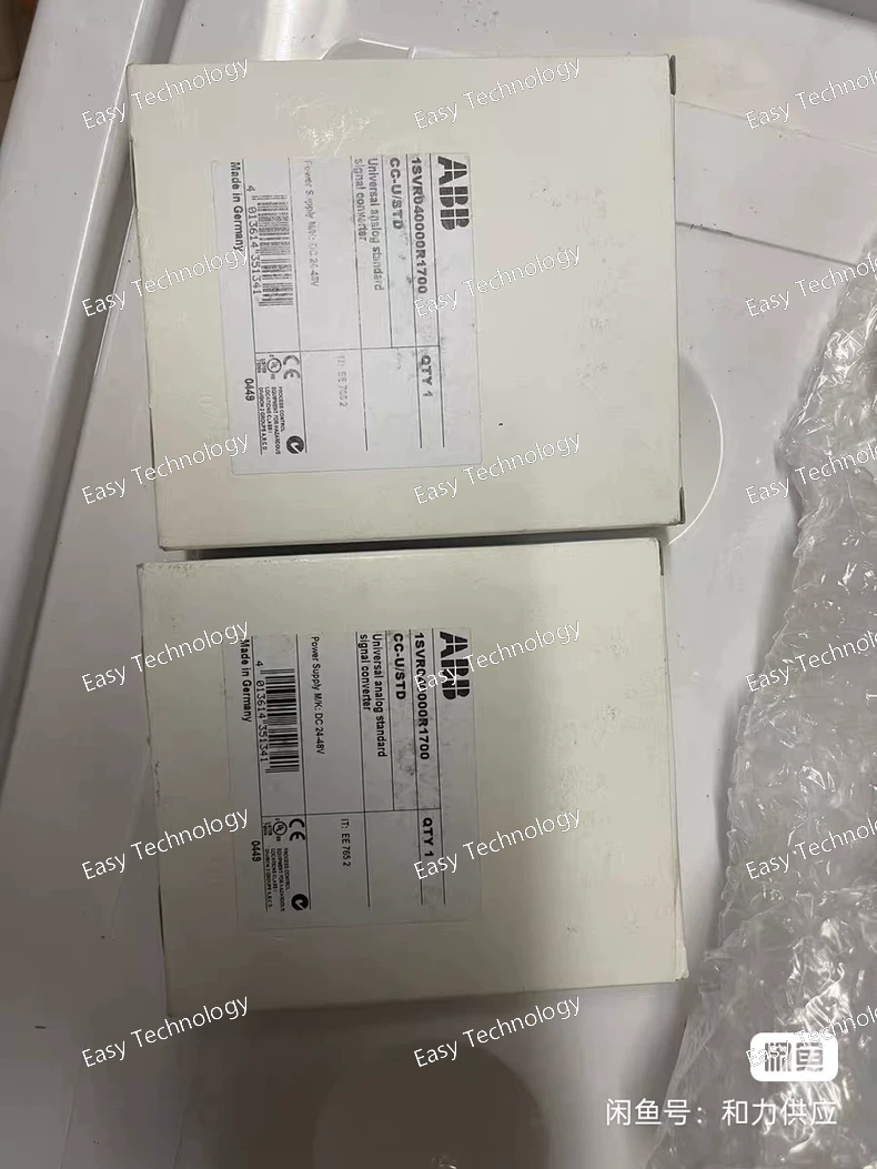
Technical Specifications / Parameters Parameter Specification Manufacturer Order Code 1SVR040000R01700 Catalogue Type CC-U/STD Brand / Series ABB CR-U Series (Universal Monitoring Relays) Device Type Universal Monitoring Relay (Switching Amplifier) with 2 Adjustable Setpoints Input Signal Type DC Voltage or True RMS AC Voltage. Input Voltage Range Typically 0...10V DC or 0...500V AC (selectable or via different models). Input Impedance High impedance (>100kΩ for voltage inputs) to avoid loading the signal source. Setpoint Adjustment Via two front-panel potentiometers for independent adjustment of upper and lower switching thresholds. Monitoring Function Configurable as a window comparator (output active when signal is inside a set range) or outside a range comparator. This provides hysteresis to prevent output chattering. Output Relay 1 Changeover (CO) Contact (SPDT: 1 NO + 1 NC) • Contact Rating: Typically 6A / 250V AC (resistive load). Output Logic Configurable (e.g., relay energized when condition is met, or de-energized). Power Supply Separate auxiliary supply, typically 24...240V AC/DC (wide-range). Response Time Typically < 500ms. Status Indication LEDs for Power, Input Signal Present, and Output Status. Mounting DIN Rail Mounting (35mm). Module Width 22.5 mm (1 module width, compact). Operating Temperature -25°C to +55°C. Front Protection Degree IP40. Standards & Approvals IEC/EN 60255, UL 508, CSA C22.2 No. 14, CE, cULus. Typical Applications • Level monitoring using a potentiometric sensor (e.g., in tanks). • Pressure or flow switch using a 4-20mA/0-10V transmitter (with external resistor). • Speed monitoring using a tachogenerator. • Over/under-voltage monitoring of DC bus or battery banks. • General-purpose alarm annunciator for any analog signal.
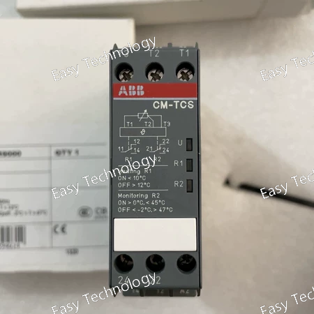
Technical Specifications / Parameters Parameter Specification Manufacturer Order Code 1SVR430740R9000 Catalogue Type CM-TCS.26 Brand / Series ABB CM-TCS Series (Digital Timer Relays) Device Type Digital Timer Relay (Time Delay Relay) Operating Modes Multiple modes, typically including: • On-Delay (Delay on Make) • Off-Delay (Delay on Break) • Interval / One-Shot • Flicker (Flashing) • Symmetrical / Asymmetrical Pulse Output Time Delay Range Wide range, adjustable via front DIP switches or rotary dials. Typically from 0.1 seconds up to 100 hours (selectable ranges). Setting Accuracy High accuracy (typically ±0.5% of set value or better). Supply Voltage (Us) Wide-range 24...240V AC/DC (auto-sensing). Input Signal The supply voltage also serves as the control signal. Timer starts upon application (for on-delay) or removal (for off-delay) of supply voltage. Output Relay 1 Changeover (CO) Contact (SPDT - 1 NO + 1 NC) • Contact Rating: Typically 8A / 250V AC (resistive load). Reset Function Instantaneous reset upon power interruption (for on-delay). For off-delay, behavior depends on the specific mode. Status Indication LEDs for Power (Supply) and Output Status (shows when the output relay is energized). Time Setting Method Via rotary DIP switches or thumbwheel switches on the front for selecting the time multiplier (e.g., x0.1s, x1s, x1min) and digit dials for setting the precise value. Mounting DIN Rail Mounting (35mm). Module Width 22.5mm (1 module width). Operating Temperature -20°C to +60°C. Front Protection Degree IP40. Standards & Approvals IEC/EN 60255, UL 508, CSA C22.2 No. 14, CE, cULus. Typical Applications • Motor Star-Delta starting sequence control. • Conveyor belt sequencing and interlocking. • Pump duty cycling (alternating pumps). • Lighting control (stairwell lighting, signage). • Machine tool control cycles (dwell times, cool-down periods). • Ventilation system control (delayed shut-off).
 TEL: Grace +86 13600179521
  Mail: info@hongkongeasy.com jilineasyyi@outlook.com
 Q Q:615739355
 ADDRESS:Unit 12, 20th Floor, Good View Commercial Centre, 2-16 Garden Street, Mong Kok, Hong Kong
 whats app


