
Industrial Controller
All product are in stock,guaranteed delivery within 3-7 days.


PRODUCT
PICTURE
BRAND
DESCRIBE
STOCK
DOWNLOAD
Parameters Category Parameter Specification for CA4-10 General Product Type Multifunction Timer Relay (Analog Setting) Series CA4 Series Primary Function (Typical) On-Delay (TON) Power Supply Supply Voltage (Uₛ) 24-240 V AC / 24-240 V DC (Universal, auto-sensing) Frequency 50/60 Hz (for AC supply) Power Consumption Approx. 2.5 VA / 1.5 W (typical) Timing Characteristics Setting Method Potentiometer (screwdriver adjustable) Time Range Typically 0.1 sec - 30 min or 0.5 sec - 10 hours (varies by model; verify via marking) Repeat Accuracy ≤ ±1% of set value (typical) Reset Time ≤ 50 ms (typical) Input / Trigger Start Signal Voltage applied across terminals A1-A2 (power supply also acts as trigger in basic mode). Output Output Type Electromechanical Relay Contact Configuration SPDT (1 Changeover) or DPDT (2 Changeover) (1 NO + 1 NC) Contact Rating (Resistive) 8 A at 250 V AC 5 A at 30 V DC Electrical Life ≥ 100,000 cycles (at rated load) Mechanical Life ≥ 10 million cycles Indicators LEDs Green: Power On Red/Orange: Output Energized Terminals Terminal Type Screw clamp terminals Wire Size 0.5 - 2.5 mm² (AWG 20-14) Torque 0.5 - 0.6 Nm Standards & Approvals Compliance Standards IEC/EN 61812-1, UL 508, CSA C22.2 Certifications CE, cULus, CCC Environmental Operating Temperature -20°C to +55°C (with no icing) Storage Temperature -40°C to +70°C Altitude Up to 2000 m Pollution Degree PD 2 Protection Degree IP40 (front), IP20 (terminals) Physical & Mounting Mounting 35 mm symmetrical DIN rail (EN 60715) Dimensions (W×H×D) Approx. 22.5 × 76 × 90 mm (1 module wide) Weight Approx. 0.13 kg
Parameters Category Parameter Specification for MS325-2.5 General Product Type Manual Motor Starter / Motor Protection Circuit Breaker Series MS325 (System Pro M compact®) Rated Operational Current (Iₑ) 2.5 A (at 400V AC, AC-3 duty) Rated Voltages & Duty Rated Insulation Voltage (Uᵢ) 690 V AC / 250 V DC Utilization Category AC-3: Squirrel cage motor switching AC-1: Resistive load switching Rated Operational Voltage (Uₑ) Up to 400 V AC, 50/60 Hz (for motor loads) Switching & Protection Rated Operational Power (Pₑ) ~1.1 kW (at 400V AC, 3-phase) Overload Protection Thermal (Bi-metal), Class 10 Short-Circuit Protection Magnetic (Solo-trip), typically "C" curve (5-10 x Iₙ). Confirm via full order code. Rated Short-Circuit Breaking Capacity (Iᶜⁿ) Typically 6 kA (at 400V AC, according to EN 60947-2) Mechanical & Electrical Number of Poles 3 Poles (for 3-phase motors) Control Method Manual toggle operation (I-O lever) Trip Indication Visual flag (red) Electrical Life (AC-3) ≥ 10,000 cycles Mechanical Life ≥ 20,000 cycles Terminals Terminal Type Cage clamp (spring) terminals for quick wiring. Acceptable Cable Size Solid/Fine-stranded: 0.75 - 4 mm² With ferrule: 0.75 - 2.5 mm² Torque Not required (spring clamp) Standards & Approvals Compliance Standards IEC/EN 60947-1, IEC/EN 60947-2, IEC/EN 60947-4-1 Certifications CE, cULus, CCC, etc. Environmental Operating Temperature -25°C to +60°C (calibrated at +40°C) Storage Temperature -40°C to +70°C Altitude Up to 2000 m without derating Pollution Degree PD 2 Protection Degree IP20 (as mounted in enclosure) Physical & Mounting Mounting 35 mm top-hat DIN rail (EN 60715) Dimensions (W×H×D) Approx. 53 × 77 × 67 mm (3-pole unit) Weight Approx. 0.14 kg Motor Data Reference Motor Power at 400V 3ph Approx. 1.1 kW (~1.5 HP) Motor Power at 230V 3ph Approx. 0.55 kW (~0.75 HP) Motor Power at 230V 1ph Approx. 0.37 kW (~0.5 HP)
Parameters Category Parameter Specification for MS325-0.16 General Product Type Manual Motor Starter (MMS) with thermal overload protection Series MS325 Rated Operational Current (Iₑ) 0.16 A (at 400V AC, AC-3) Rated Voltages & Duty Rated Insulation Voltage (Uᵢ) 690 V AC Utilization Category AC-3: Squirrel cage motor switching AC-1: Resistive load switching Rated Operational Voltage (Uₑ) Up to 400 V AC, 50/60 Hz (for motor loads) Switching Capacity Rated Operational Power (Pₑ) ~0.06 kW (at 400V AC, 3-phase) Rated Service Short-Circuit Breaking Capacity (Iᵥ) Typically 1.5 kA (at 400V AC, with back-up fuse class gG/gL) Protection Characteristics Overload Protection Thermal, bi-metal release Trip Class Class 10 (as per IEC 60947-4-1) Setting Range Fixed at 0.16A (non-adjustable for this model) Ambient Temp. Compensation Yes, from -20°C to +60°C Mechanical & Electrical Number of Poles 3 Poles (for 3-phase motors) Control Method Manual toggle/rocker operation Auxiliary Contacts Not included (available as add-on accessory modules) Electrical Life (AC-3) ≥ 20,000 cycles Mechanical Life ≥ 30,000 cycles Terminals Terminal Type Screw clamp terminals Acceptable Cable Size 0.5 - 2.5 mm² (flexible with ferrule) / 0.5 - 4 mm² (solid) Torque 0.5 - 0.6 Nm Standards & Approvals Compliance Standards IEC/EN 60947-1, IEC/EN 60947-4-1 Certifications CE, cULus, CCC, etc. (Market dependent) Environmental Operating Temperature -25°C to +60°C Storage Temperature -40°C to +70°C Altitude Up to 2000 m without derating Pollution Degree PD 2 Protection Degree IP20 (as mounted in enclosure) Physical & Mounting Mounting 35 mm symmetrical DIN rail (EN 60715) Dimensions (W×H×D) Approx. 45 × 80 × 60 mm (3-pole unit) Weight Approx. 0.12 kg
Parameters Category Parameter Specification General Product Type 3-pole AC Contactor Series A-line (AX/AF series) Rated Operational Current (Iₑ) 80 A at AC-3, 400V Rated Voltages Rated Insulation Voltage (Uᵢ) 690 V Rated Operational Voltage (Uₑ) AC 230V, 400V, 500V, 690V Switching Capacity AC-3 Duty (Squirrel cage motors) 37 kW at 400V AC 55 kW at 690V AC AC-1 Duty (Resistive loads) 80 A Maximum Making Capacity 12 × Iₑ (960 A) Maximum Breaking Capacity 10 × Iₑ (800 A) Mechanical Characteristics Number of Poles 3 Main Poles (NO) Auxiliary Contacts Up to 4 NO + 4 NC (with add-on blocks) Mechanical Life 10 million operations Electrical Life (AC-3) ≥ 300,000 operations Coil Data Coil Voltage (Standard) AC: 24V, 48V, 110V, 230V, 400V, 500V DC: 24V, 48V, 110V, 220V Power Consumption Pick-up: ~60 VA / 30 W Holding: ~8 VA / 3.5 W (typical for AC coil) Electrical Characteristics Rated Conditional Short-Circuit Current (Iq) 10 kA (with appropriate fuse/breaker) Overload Capacity 8 × Iₑ for 10 seconds Frequency 50/60 Hz Terminals Main Circuit Terminals Screw clamp type, accepts cables up to 35 mm² Auxiliary Terminals Spring clamp type, accepts cables up to 2.5 mm² Standards & Approvals Compliance Standards IEC 60947-4-1, EN 60947-4-1 Certifications CE, cULus, CCC, etc. Environmental Operating Temperature -25°C to +60°C (with no icing) Storage Temperature -40°C to +70°C Altitude Up to 2000 m without derating Pollution Degree PD 3 Protection Degree IP20 (finger-safe terminals) Physical Dimensions (W×H×D) Approx. 90 × 146 × 121 mm (without accessories) Weight Approx. 0.9 kg (base unit) Mounting Mounting Method Panel mounting on 35 mm DIN rail (EN 60715) or screw mounting Mounting Position Any orientation

Parameters Category Parameter Typical Specification / Value for SPAM150C-CA General Product Family & Type SPAM150C - Numerical Motor Protection Relay Hardware Variant -CA (Specific I/O & Power Supply Configuration) Standard IEC 60255, IEC 61850, IEEE C37.90 Power Supply Operational Voltage Common: 24-48 V DC, 48-110 V DC, 110-250 V DC, or 110-230 V AC (Order-specific) Current Inputs Rated Current (Iₙ) 1 A or 5 A (Defined by ordering code) Thermal Withstand Continuous: 2 x Iₙ; 1 sec: 100 x Iₙ Voltage Inputs Rated Voltage (Uₙ) 100-120 V or 190-230 V line-to-neutral (via VT) Binary Inputs (BI) Number Typically 12-16 (Configurable in groups) Output Relays (BO/PO) Trip/Alarm Relays Typically 8-10 (Mix of fast, high-capacity and signal relays) Analog Inputs Temperature (RTD) 4-6 dedicated inputs for Pt100 sensors (Bearing/Stator temp.) Human-Machine Interface Display Graphical LCD with backlight Local Control Keypad for navigation and control Communication Primary Protocol IEC 61850-8-1 (MMS & GOOSE) Serial Protocols Modbus RTU (RS485), often includes DNP3 or IEC 60870-5-103 Physical Ports 1 x Electrical Ethernet (RJ-45), 1-2 x RS485 Serial Ports Core Protection Functions (ANSI) Thermal Model 49 (Thermal Overload) with start-up and stall supervision Overcurrent 50/51 (Phase OC), 50N/51N/67N (Earth Fault), 46 (Unbalance) Motor-Specific 14/66 (Stall/Locked Rotor), 37 (Undercurrent), 32 (Under/Over Power) Other 27/59 (Under/Overvoltage), 81 (Frequency), 38/49T (Bearing Temp.) Monitoring & Metering Measurements I, V, P, Q, S, PF, Energy, Motor Starts, Run-time Recording Oscillographic Fault Recorder, Event Log (SOE), Trip Log Environmental Operating Temperature -20°C to +70°C (Standard industrial range) Housing Compact, for panel mounting.
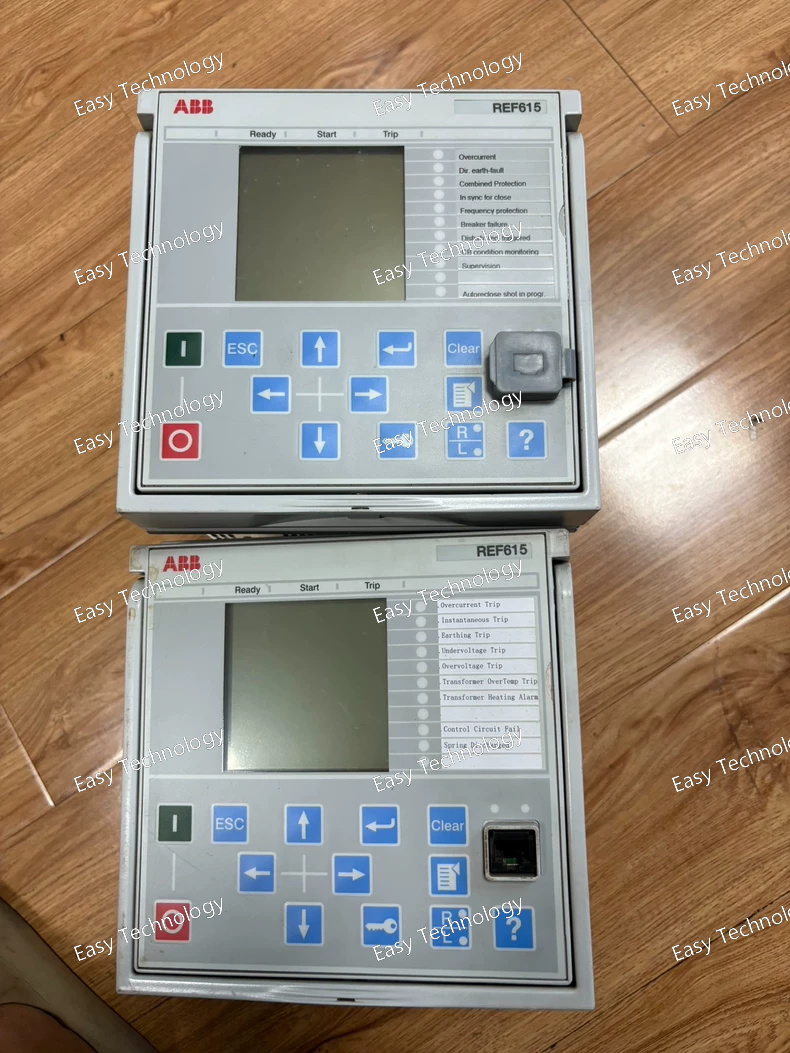
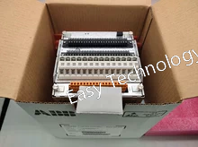
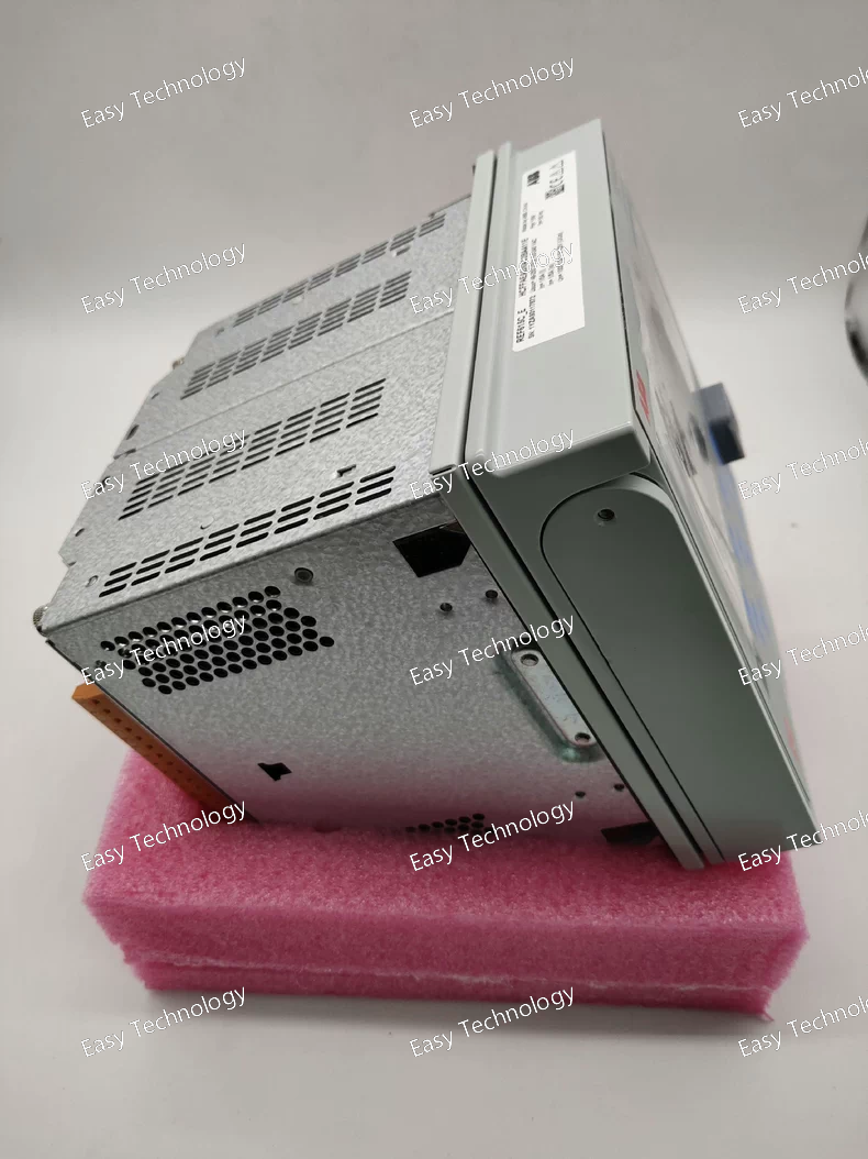
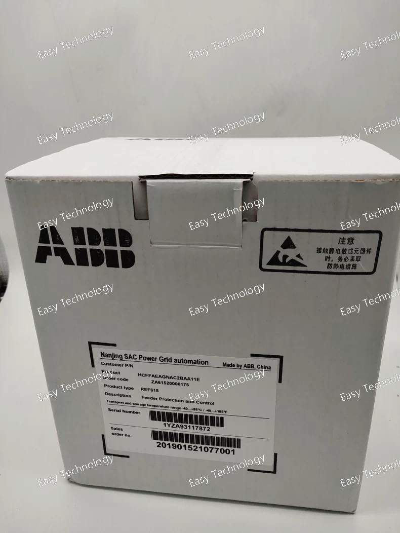
Category Parameter Specification / Value Remarks Switchgear Platform Model & Type UniGear ZS1 Air-insulated, metal-clad, withdrawable Rated Voltage (Uₐ) 12 kV / 17.5 kV / 24 kV Standard for ZS1 platform. Project-specific. Rated Frequency 50 Hz / 60 Hz Project-specific. Insulation Level 24 kV / 28 kV / 36 kV (Power freq.) 60 kV / 75 kV / 95 kV (Impulse) Corresponds to 12/17.5/24 kV ratings. Primary Equipment Circuit Breaker Type Vacuum Circuit Breaker (VCB) Typically ABB VD4 series or equivalent. Rated Normal Current (Iₐ) 1250 A Continuous current rating for main busbar and breaker. Rated Short-Circuit Breaking Current (Iₖ) 25 kA Symmetrical breaking capacity at rated voltage. Rated Short-Time Withstand Current (Iₖ) 25 kA (3 s) Thermal withstand capability. Mechanical Endurance 30,000 operations Typical for VCB in this class. Withdrawal Type Fixed Breaker (Disconnectable) Code "B": Fixed, but can be isolated. Protection & Control Relay Type REF615 Feeder Protection Relay Multi-function digital protection IED. Protection Functions Overcurrent, Earth Fault, Thermal, Voltage, etc. As per REF615's "AG" variant configuration. Communication Protocols IEC 61850-8-1 (MMS/GOOSE), IEC 60870-5-103, Modbus Standard for REF615 relay. Instrument Transformers Current Transformers Quantity: 2 Sets (Cores) Accuracy Class: Typically 5P20 for protection Code "B". Specific ratio (e.g., 2000/1A) defined in project drawings. Voltage Transformers None Code "N". Auxiliary Supplies Control & Protection Supply 110 V DC Code "N". Standard for substation battery systems. Heating & Lighting Supply 230 V AC, 1-phase, 50/60 Hz Code "A". Space Heater Power Typically 100 - 300 W Dependent on cubicle size and climate class. Mechanical & Safety Degree of Protection (IP) IP4X (Internal compartment) IP2X / IP3X (Front) Standard for UniGear ZS1. Internal Arc Classification (IAC) IAC AFLR (Optional) If specified for the project. Earthing Switch Included Standard for feeder panels. Shutters Automatic, self-closing For busbar and cable compartment safety. Mechanical Interlocks Full 5-point interlocking Prevents incorrect operations. Connections Busbar System Single Busbar Standard for ZS1. Cable Connection Standard (Bottom entry) Code "A1". For single-core or 3-core cables. Cable Termination Suitable for up to 240 mm² (Cu) / 300 mm² (Al) Typical maximum. Physical & Environmental Panel Dimensions (H x W x D) Approx. 2300 x 800 x 1700 mm (Typical) Exact dimensions in project drawings. Weight Approx. 1000 - 1300 kg Fully equipped. Operating Temperature -5°C to +40°C (Standard indoor) For normal service. Paint / Finish RAL 7035 (Light Grey) Code "D". Standard color. Special Notes Configuration Note "X" denotes special version Indicates non-standard modifications per customer requirements.
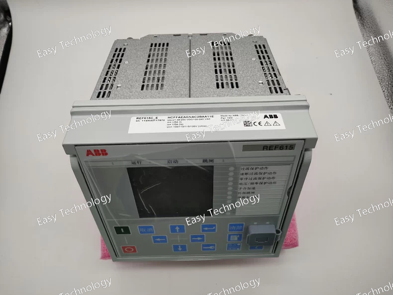
Parameters Category Parameter Typical Specification / Value for REF615C-C General Product Level "C" (Control) Hardware Variant -C (Specific I/O & Comm Configuration) Standards Compliance IEC 60255, IEC 61850, IEEE C37.90, IEC 61000-4 (EMC) Power Supply Operational Voltage Common Ranges: 24-48 V DC, 48-110 V DC, 110-250 V DC, or 110-230 V AC (Ordering code specific) Inputs Current Inputs (Iₙ) 1 A or 5 A (Defined by hardware ordering code) Voltage Inputs (Uₙ) 100-120 V or 190-230 V line-to-neutral (via Voltage Transformers) Binary Inputs (BI) Typically 16 (Configurable in groups for 24-250V DC / 110-230V AC) Outputs Output Relays Trip/Close (PO): Typically 6 (High-capacity) Signal/General (BO): Typically 8 Human-Machine Interface Display Standard LCD with status LEDs Local Control Basic navigation keypad Communication Primary Protocol IEC 61850-8-1 (MMS & GOOSE) Serial Protocols IEC 60870-5-103, Modbus RTU Optional Protocol DNP3 (Serial or over Ethernet) Physical Ports 1 x Electrical Ethernet (RJ-45), 1 x Optical Ethernet (ST), 2 x RS485 Serial Ports Core Protection Functions (ANSI) Overcurrent 67 (Dir. OC), 50/51 (Inst./Time OC), 50N/51N (Inst./Time EF), 67N (Dir. EF) Other Protection 27 (Undervoltage), 59 (Overvoltage), 49 (Thermal Overload), 79 (Autoreclosing), 81U/f (Frequency), 46 (Unbalance) Environmental Operating Temperature -25°C to +70°C (Standard industrial range) Housing Compact, IP40/IP52, for panel mounting.
Parameters Category Parameter Specification / Value for REF615E_G General Product Level "E" (Enhancement) Hardware Variant _G (Graphic Display & Enhanced Keypad) Standard IEC 60255, IEC 61850, IEEE C37.90 Power Supply Operational Voltage Ranges Typically: 24-48 V DC / 48-110 V DC / 110-250 V DC or 110-230 V AC (Ordering code specific) Inputs Current Inputs (I<sub>n</sub>) 1 A or 5 A (hardware dependent) Voltage Inputs (U<sub>n</sub>) 100-120 V or 190-230 V line-to-neutral (via VT) Binary Inputs (BI) Typically 16 (configurable in groups for different voltage levels) Outputs Output Relays Trip/Close (PO): Typically 6 Signal (BO): Typically 8 Human-Machine Interface Display Large, high-resolution Graphical LCD Local Control Enhanced keypad for full navigation and control Communication Primary Protocol IEC 61850-8-1 (MMS & GOOSE) Serial Protocols IEC 60870-5-103, Modbus RTU Optional Protocol DNP3 (serial or Ethernet) Physical Ports 1 x Electrical Ethernet (RJ-45), 1 x Optical Ethernet (ST), 2 x RS485 Protection Functions (Key ANSI) Overcurrent 67/67N (Dir. OC/EF), 50/51 (Inst./Time OC), 50N/51N (Inst./Time EF), 50BF (CB Fail) Other Protection 27 (Undervoltage), 59 (Overvoltage), 49 (Thermal O/L), 79 (Autorecloser), 81U/f (FreQ), 46 (Unbalance) Environmental Operating Temperature Standard: -25°C to +70°C Housing & Mounting Compact, IP40/IP52 rated, for panel mounting.
Parameters Category Parameter Typical Specification / Value Power Supply Operational Voltage 24-48 V DC / 48-110 V DC / 110-250 V DC or 110-230 V AC Current Inputs Rated Current (I<sub>n</sub>) 1 A or 5 A (hardware specific) Thermal Withstand Continuous: 4 x I<sub>n</sub>; 1 sec: 100 x I<sub>n</sub> Voltage Inputs Rated Voltage (U<sub>n</sub>) 100-120 V line-to-neutral or 190-230 V line-to-neutral (via VT) Binary Inputs (BI) Number Typically 16 (including 1 for CB position) Voltage 24-250 V DC / 110-230 V AC (configurable in groups) Output Relays (BO/PO) Trip/Close Relays (PO) Typically 6 (fast, high-breaking capacity) Signal Relays (BO) Typically 8 (general purpose) Communication Primary Protocol IEC 61850-8-1 (MMS & GOOSE) Serial Protocols IEC 60870-5-103, Modbus RTU Optional Protocols DNP3 (serial or over Ethernet) Ports 1 x Electrical Ethernet, 1 x Optical Ethernet (ST), 2 x RS485 serial Protection Functions Key ANSI/IEC Codes 67/67N (Dir. OC/EF), 50/51 (OC), 50N/51N (EF), 59 (OV), 27 (UV), 49 (Thermal), 46 (Phase Unbalance), 79 (Recloser), 81 (U/f), 50BF (CB Failure) Standards Compliance IEC 60255, IEEE C37.90, IEC 61000-4 (EMC), IEC 60870, IEC 61850
Technical Specifications / Parameters Parameter Specification Manufacturer Model REF615E-E Product Family / Series ABB Relion® 615 Series (Feeder Protection - "E" Variant) Device Type Compact Numerical Feeder Protection Relay (Economy/Essential Version) Housing Compact case (similar in size to the "K" case, optimized for space efficiency). Key Protection Functions Core protection functions typically include: • Overcurrent Protection (50/51, 50N/51N) – Primary function for phase and earth faults. • Directional Overcurrent (67/67N) – May be available or as an option. • Sensitive Earth-Fault Protection • Thermal Overload (49) for cable protection • Breaker Failure Protection (50BF) – May be standard or optional. • Under/Overvoltage (27/59) • Auto-reclosing (79) – Often a key optional feature. Control & Monitoring Streamlined compared to full versions: • Basic programmable logic • Event recorder • Fault recorder (disturbance recorder) – May have limited duration. • Essential measurements: V, I, P, Q, PF, Frequency. Communication Protocols Focus on essential and common protocols: • IEC 61850 – Likely supported but potentially with a reduced feature set (e.g., GOOSE may be optional). • Modbus RTU (serial) – Standard for SCADA/DCS integration. • IEC 60870-5-103 – Common in many regions. • IEC 61850 MMS, DNP3, Modbus TCP may be optional. Hardware I/O (Typical) Reduced I/O count compared to REF615J/K: • Binary Inputs: ~6 (24-250V DC) • Binary Outputs (Relays): ~4-6 (Form-A contacts) • Analog Inputs: 4 current (1A/5A), voltage inputs may be optional or fixed. • Communication Ports: 1-2 serial ports (RS485), Ethernet may be optional. Human-Machine Interface (HMI) • LCD display (potentially smaller or monochrome) for status and measurements. • Front navigation keys. • Essential status LEDs. Power Supply Standard wide-range options: 24-48/60V DC or 110-240V AC/DC. Standards & Certifications IEC 60255 (core), IEC 61850 (if equipped), UL 508, CE. Mounting DIN Rail Mounting (primary) or panel mounting. Configuration Software Configured using ABB's PCM600 software (potentially with a license or feature key for advanced functions).
Technical Specifications / Parameters Parameter Specification Manufacturer Model REF615J Product Family / Series ABB Relion® 615 Series (Feeder Protection) Device Type Numerical Feeder Protection and Control Relay Housing "J" Case (Standard depth design, offering a balanced profile for panel integration). Key Protection Functions • Overcurrent Protection (50/51, 50N/51N) with multiple independent, time-delayed or instantaneous stages • Directional Overcurrent Protection (67/67N) • Sensitive Directional Earth-Fault Protection • Thermal Overload Protection (49) for cables and motors • Phase Imbalance / Negative Sequence (46) • Breaker Failure Protection (50BF) • Under/Overvoltage (27/59) & Under/Overfrequency (81O/U) • Auto-reclosing (79) (for overhead lines) • Inrush Current Restraint (to prevent transformer magnetizing inrush misoperation) Control & Monitoring • Advanced Programmable Logic using CAP (Configuration and Planning) editor in PCM600 • Sequence of Events (SOE) Recorder with high-resolution time-stamping • Disturbance Recorder (Fault Recorder) for detailed fault analysis • Comprehensive Metering: V, I, P, Q, PF, Energy, Harmonics, etc. • Circuit Breaker Condition Monitoring (operating time, trip count, wear estimation) Communication Protocols • IEC 61850 (Edition 2) for station bus communication (MMS, GOOSE for high-speed peer-to-peer signaling) • IEC 60870-5-103 & IEC 60870-5-104 • Modbus RTU (serial) & Modbus TCP/IP (over Ethernet) • DNP3 (Serial & TCP) • IEC 61850 over MMS for SCADA integration Hardware I/O (Typical Configuration) • Binary Inputs: 9-12 (24-250V DC, configurable) • Binary Outputs (Relays): 8-10 (Form-A or Form-C contacts) • Analog Inputs: 4 current (1A/5A), 4 voltage (100-120V line-to-neutral) • Ethernet Ports: 2 or 4 (RJ45, copper or optional fiber) • Serial Ports: 1-2 (RS485/RS232) Human-Machine Interface (HMI) • High-contrast graphical LCD display • Intuitive menu navigation with front-panel keys • LED Indicators for status, alarms, and trip • Multilingual text support Power Supply Wide-range options: 24-48V DC, 60-250V DC, or 110-240V AC/DC. Standards & Certifications IEC 60255, IEC 61850, IEEE C37.90, UL 508, CE, DNV, and other industry-specific certifications. Mounting Panel mounting (flush or surface) or DIN Rail Mounting (with optional kit). Configuration Software ABB PCM600 (Protection and Control IED Manager) for parameter setting, logic configuration, and commissioning.
Technical Specifications / Parameters Parameter Specification Manufacturer Model REF615K Product Family / Series ABB Relion® 615 Series (Feeder Protection) Device Type Numerical Feeder Protection and Control Relay Housing Compact "K" Case (Depth-reduced design for space-constrained panels). Key Protection Functions • Overcurrent Protection (50/51, 50N/51N) with multiple independent stages • Directional Overcurrent Protection (67/67N) • Earth-fault Protection (Sensitive and directional) • Phase Reversal (46) • Thermal Overload (49) for motor/cable protection • Breaker Failure Protection (50BF) • Under/Overvoltage (27/59) & Under/Overfrequency (81) • Auto-reclosing (79) Control & Monitoring • Programmable Logic (PLC-like) via CAP (Configuration and Planning) tools • Sequence of Events (SOE) Recorder • Disturbance Recorder (Fault recorder) • Measurement of V, I, P, Q, PF, Hz, etc. • Circuit Breaker Monitoring (wear, trip count) Communication Protocols • IEC 61850 (Edition 2) for station-level communication (MMS, GOOSE) • IEC 60870-5-103 & IEC 60870-5-104 • Modbus RTU & TCP/IP • DNP3 (Serial & TCP) Hardware I/O (Typical) • Binary Inputs: 9 (24-250V DC) • Binary Outputs (Relay): 8 (form-A contacts) • Analog Inputs: 4 current (1A/5A), 4 voltage (100-120V) • Ethernet Ports: 2 or 4 (RJ45, for IEC 61850/Modbus TCP) • Serial Ports: 2 (RS485/RS232) Human-Machine Interface (HMI) • Large, high-resolution graphical LCD display • Multilingual text support • Front-face navigation keys and LED indicators Power Supply Wide-range 24-48/60V DC or 110-240V AC/DC. Standards & Certifications IEC 60255, IEC 61850, IEEE C37.90, UL 508, CE, DNV-GL, ATEX (for specific variants). Mounting Panel or DIN Rail Mounting (optional bracket).
 TEL: Grace +86 13600179521
  Mail: info@hongkongeasy.com jilineasyyi@outlook.com
 Q Q:615739355
 ADDRESS:Unit 12, 20th Floor, Good View Commercial Centre, 2-16 Garden Street, Mong Kok, Hong Kong
 whats app


