
Industrial Controller
All product are in stock,guaranteed delivery within 3-7 days.


PRODUCT
PICTURE
BRAND
DESCRIBE
STOCK
DOWNLOAD
Parameters Category Parameter Specification for CA5-04E General Product Type Multifunction Digital Timer Relay (Analog Potentiometer Setting) Series CA5 Series Display None (LED indicators only) Setting Method Analog Potentiometer + Range Multiplier Switch DIN Modules 4 modules (approx. 72 mm wide) Power Supply Supply Voltage (Uₛ) 24-240 V AC / 24-240 V DC (Universal) Frequency 50/60 Hz (AC) Power Consumption ≤ 4 VA / 3 W Timing Characteristics Time Setting 1 x Potentiometer (continuously adjustable) + 1 x Range Multiplier Switch Time Ranges (Multiplier) x0.1s, x1s, x10s, x1min, x10min, x1h (Typical) Overall Range 0.1 seconds to 10 hours (dependent on multiplier) Accuracy ≤ ±1% of max. range value (typical for analog setting) Repeat Accuracy High (excellent consistency for a given pot position) Reset Time ≤ 100 ms Input / Control Control Input (Terminal 7) External trigger/start/reset (function depends on mode). Function Selection Rotary Function Switch (typically with 8-12 positions: A, B, C, D, E, F, H, J, K, etc.) Output Output Type Electromechanical Relay Contact Configuration DPDT (2 Changeover) - 2 NO + 2 NC Contact Rating (Resistive) 8 A at 250 V AC 5 A at 30 V DC Electrical Life ≥ 100,000 cycles (at rated load) Mechanical Life ≥ 10 million cycles Indicators (LED) Status LEDs Green (PWR): Power On Red (OUT): Output Energized Yellow (TM): Timing in Progress Terminals Terminal Type Screw clamp terminals Wire Size 0.5 - 2.5 mm² (AWG 20-14) Torque 0.5 - 0.6 Nm Standards & Approvals Compliance Standards IEC/EN 61812-1, UL 508, CSA C22.2 Certifications CE, cULus, CCC Environmental Operating Temperature -20°C to +55°C (no icing) Storage Temperature -40°C to +70°C Altitude Up to 2000 m Pollution Degree PD 2 Protection Degree IP40 (front), IP20 (terminals) Physical & Mounting Mounting 35 mm symmetrical DIN rail (EN 60715) Dimensions (W×H×D) Approx. 72 mm (4 modules) x 90 mm x 64 mm Weight Approx. 0.25 kg
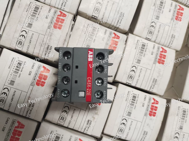
Parameters Category Parameter Specification for CA5X-04M General Product Type Digital Multifunction Timer Relay with Display Series CA5X Series Display Type Digital Numeric Display (LED/LCD) DIN Modules 4 modules (approx. 72 mm wide) Power Supply Supply Voltage (Uₛ) 24-240 V AC / 24-240 V DC (Universal, auto-sensing) Frequency 50/60 Hz (AC) Power Consumption ≤ 3.5 VA / 2.5 W Timing Characteristics Setting Method 2 Rotary Decade Switches (0-9) + 1 Multiplier Switch Time Ranges (Multiplier) x0.1s, x1s, x10s, x1min, x10min, (x1h) Setting Range 0.1s to 990min (or 0.1s to 99h with x1h range) Accuracy ≤ ±0.5% of set value ± 10 ms Resolution 10 ms Reset Time ≤ 50 ms Input / Control Control Input (Terminal) External trigger/start/reset (function depends on DIP settings) Function Selection 8-position DIP switch for mode, range, reset behavior, etc. Output Output Type Electromechanical Relay Contact Configuration DPDT (2 Changeover) - 2 NO + 2 NC Contact Rating (Resistive) 8 A at 250 V AC 5 A at 30 V DC Minimum Load 10 mA at 5 V DC Electrical Life ≥ 100,000 cycles (rated load) Mechanical Life ≥ 10 million cycles Indicators Display 3/4-digit numeric display for set/actual time Status LEDs Green (PWR): Power On Red (OUT): Output Energized Yellow (TM): Timing in Progress Terminals Terminal Type Screw clamp terminals Wire Size 0.5 - 2.5 mm² (AWG 20-14) Torque 0.5 - 0.6 Nm Standards & Approvals Compliance Standards IEC/EN 61812-1, UL 508, CSA C22.2 Certifications CE, cULus, CCC Environmental Operating Temperature -20°C to +55°C (no icing) Storage Temperature -40°C to +70°C Altitude Up to 2000 m Pollution Degree PD 2 Protection Degree IP40 (front), IP20 (terminals) Physical & Mounting Mounting 35 mm symmetrical DIN rail (EN 60715) Dimensions (W×H×D) Approx. 72 mm (4 modules) x 90 mm x 64 mm Weight Approx. 0.18 kg

Parameters Category Parameter Specification for CAL18-11B General Type Heavy-Duty Precision Limit Switch with Metal Lever Series CAL18 Series Contact Configuration SPDT (1 NO + 1 NC) Actuator Type Metal Lever, Side Rotary Roller, Right-Angle Return (Type "B") Electrical Ratings Rated Insulation Voltage (Ui) 500 V AC/DC Utilization Category (AC) AC-15: 10 A at 250 V AC, cos φ = 0.65 Utilization Category (DC) DC-13: 0.3 A at 250 V DC, L/R = 40 ms Rated Operational Current (Ie) 10 A, 250 V AC 0.3 A, 250 V DC Rated Thermal Current (Ith) 10 A Switching Capacity (AC) Make/Break: 10A, 250V, cos φ=0.65 Switching Capacity (DC) Make/Break: 0.3A, 250V, L/R=40ms Electrical Life > 1 x 10⁶ operations (at rated load) Mechanical Characteristics Mechanical Life > 10 x 10⁶ operations Operating Force Approx. 3.5 N (typical at roller) Release Force ≥ 0.6 N Pretravel ~15° (angle for lever to start moving contacts) Overtravel > 45° (maximum permissible travel beyond operating point) Repeat Accuracy ±0.5° (angular, typical) Terminals Connection Type Screw Clamp Terminals Terminal Capacity 2 x 1.5 mm² or 1 x 2.5 mm² (solid/fine-stranded) Torque 0.5 - 0.6 Nm Environmental & Construction Housing Material Thermoplastic (PBT) or Die-Cast Zinc (varies) Protection Degree (IP) IP65 (Dust-tight & protected against water jets from any direction) Operating Temperature -25°C to +85°C (Ambient) Storage Temperature -40°C to +100°C Ambient Humidity 5% to 93% RH (non-condensing) Vibration Resistance 10 - 55 Hz, 0.75 mm amplitude Shock Resistance 30 G, 11 ms duration Actuator Details Lever Material Steel or Zinc Alloy Roller Material Nylon or Metal (standard) Lever Length (Approx.) ~40 mm (from pivot to roller center - verify with catalog) Mounting Mounting Holes 2 x Ø4.5 mm (for M4 screws) on standardized footprint Mounting Torque 1.2 - 1.5 Nm for mounting screws Standards & Approvals Compliance Standards IEC 60947-5-1, EN 60947-5-1 Certifications CE, cULus
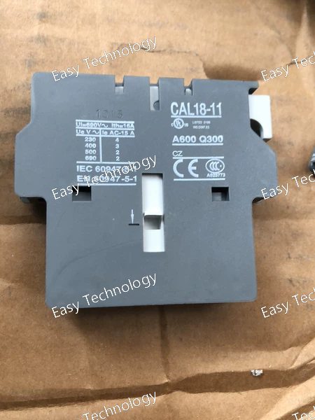
Parameters Category Parameter Specification for CAL18-11 General Type Heavy-Duty, Precision Snap-Action Limit Switch Series CAL (Component Automation) Series Contact Configuration SPDT (Single Pole, Double Throw) - 1 NO (Normally Open) + 1 NC (Normally Closed) Actuator Type (Typical for -11) Roller Lever, Right-Angle Return Electrical Ratings Rated Insulation Voltage (Ui) 500 V Utilization Categories (IEC 60947-5-1) AC-15: Control of electromagnetic loads (coils) DC-13: Control of DC electromagnetic loads Rated Operational Current (Ie) 10 A at 250 V AC 0.3 A at 250 V DC Rated Thermal Current (Ith) 10 A Switching Capacity AC: Make/Break: 10A, 250V, cos φ=0.65 DC: Make/Break: 0.3A, 250V, L/R=40ms Electrical Life > 1 million operations (at rated load) Mechanical Characteristics Mechanical Life > 10 million operations Operating Force Approx. 2.5 - 4 N (depends on actuator) Release Force ≥ 0.5 N Pretravel/Overtravel Specific to actuator; e.g., ~15° pretravel, ~20° overtravel for lever type. Repeat Accuracy ±0.1 mm (typical) Terminals Connection Type Screw clamp terminals Terminal Capacity Up to 2 x 1.5 mm² or 1 x 2.5 mm² Torque 0.5 - 0.6 Nm Environmental & Construction Housing Material Thermoplastic (PBT) or Die-Cast Zinc Sealing / Protection Degree IP65 (Dust-tight and protected against water jets) Operating Temperature -25°C to +85°C (Ambient) Ambient Humidity ≤ 93% RH (non-condensing) Vibration Resistance 10 - 55 Hz, 0.75 mm amplitude Shock Resistance 30 G, 11 ms Mounting & Actuator Mounting 2 x M4 mounting holes, standard footprint. Actuator Travel Varies; common lever travel is ~90° total. Actuator Options Various roller materials (Nylon, Metal), lever lengths, and return springs available. Standards & Approvals Compliance Standards IEC 60947-5-1, EN 60947-5-1 Certifications CE, cULus
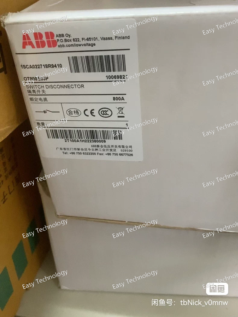
Parameters Category Parameter Specification for OT800E03P General Type Self-Powered, Draw-Out, Electromechanical IDMT Overcurrent Relay Standard Function Inverse Definite Minimum Time (IDMT) Phase Overcurrent (ANSI 51) Auxiliary Supply None Required Input Circuit Rated Frequency 50 Hz or 60 Hz Continuous Thermal Current 10 A (CT Secondary), 15 A permissible for short periods. Burden (At Setting) Approx. 4.0 to 12 VA (Varies significantly with tap setting and model). Higher than OT630. Instantaneous Withstand Up to 500 A for 0.5s (CT secondary). Settings Plug Setting (PS) / Tap Range Common Ranges: Low Range: 0.5, 0.6, 0.7, 0.8, 0.9, 1.0, 1.2, 1.5, 1.75, 2.0 A High Range: 2.0, 2.5, 3.0, 3.5, 4.0, 5.0, 6.0, 7.0, 8.0 A Time Multiplier (TMS) Typically 0.1 to 1.0 (or 0.05 to 1.0 on some models). Time-Current Characteristic ("03") Manufacturer-specific curve. Code "03" corresponds to a defined curve (e.g., Normal Inverse) in ABB's catalog. Must be verified from official tables. Output Contacts Contact Configuration DTL (Dynamically Trip-Locked): One normally-open (NO) trip contact (mechanically latched), one normally-closed (NC) alarm contact. Contact Rating (Trip Contact) Make & Carry: 30 A for 3 seconds. Break (DC Inductive): 0.25 A at 250V, L/R=40ms (50W). Break (AC): 5 A at 250V, cos φ=0.4. Contact Rating (Alarm Contact) 5 A, 250 V AC/DC (continuous). Mechanical Operation Indicators Two Flags: Red (Trip - Latched), Yellow (Disk Start). Reset Manual push-button (resets trip mechanism and red flag). Case Style Draw-Out Case (E-style) for test isolation. Mounting Panel mounting in a dedicated draw-out cradle. Accuracy & Performance Operating Time Accuracy Within ±7.5% of theoretical curve at TMS=1.0 (typical high-grade performance). Reset Time Approx. 6-15 seconds to 90% reset, depending on model and overload. Overshoot Time Minimal (< 50 ms typical). Environmental Operating Temperature -25°C to +55°C (Standard). Vibration & Shock Designed for severe substation conditions. Standards Compliance IEC 60255-3, IEEE/ANSI C37.90.
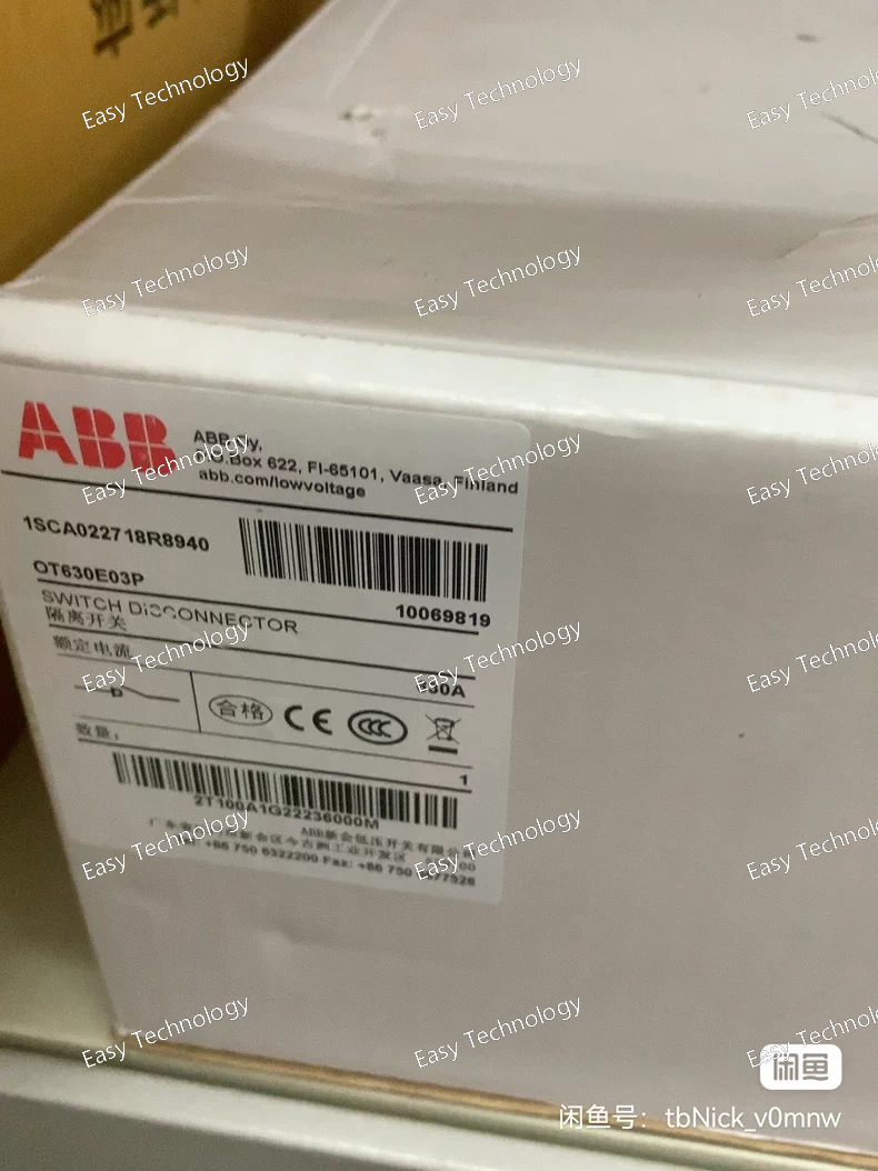
Parameters Category Parameter Specification for OT630E03P General Type Self-Powered Electromechanical Induction Disk Relay Standard Function Inverse Definite Minimum Time (IDMT) Phase Overcurrent (ANSI 51, IEC 51) Auxiliary Supply Not Required (Powered from CT secondary circuit) Input Circuit Rated Frequency 50 Hz or 60 Hz (as ordered) Thermal Rating (Continuous) Typically 10 A (CT Secondary) Burden (@ Rated Current) Approx. 3.0 to 8.0 VA (Higher than OT400, varies with plug setting) Saturation Withstands high transient currents without damage. Settings Plug Setting (PS) / Tap Range Typically 0.5 - 2.0 A or 2.0 - 8.0 A in 0.1A or 0.25A steps (e.g., 0.5, 0.75, 1.0, 1.25, 1.5, 1.75, 2.0 A). Represents 50% to 200% of CT secondary. Time Multiplier Setting (TMS) Adjustable, typically 0.1 to 1.0 (or 0.05 to 1.0) Time-Current Characteristic ("03") Specific Curve: e.g., Normal Inverse, Very Inverse, Long-Time Inverse. Must be confirmed from manufacturer tables for code "03". Output Contacts Contact Configuration DTL (Dynamically Trip-Locked): One NO trip contact that latches mechanically, plus one NC alarm contact. Contact Rating Trip Contact: Make & Carry: 30 A for 3s; Break: 0.2 A at 250 V DC (inductive). Alarm Contact: 5 A continuous. Mechanical Operation Indicator Two mechanical flags: Red for trip operation (latched), Yellow for disk start indication. Reset Manual push-button to reset the tripping mechanism and red flag. Case Flush-mounted, draw-out case for easy testing without disconnecting wiring. Mounting Panel Mounting Accuracy Operating Time Within ±10% of the theoretical curve value at TMS=1.0. Reset Time Typically < 10 seconds (for 90% reset) Environmental Operating Temperature -25°C to +55°C Vibration & Shock Designed for severe switchgear environments. Standards Compliance IEC 60255-3, ANSI/IEEE C37.90
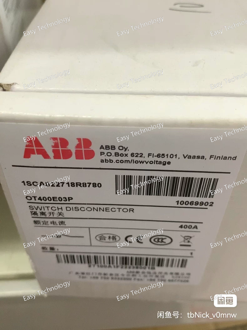
Parameters Category Parameter Specification for OT400E03P General Type Self-Powered, Electromechanical, Induction Disk/Cup, Time-Overcurrent Relay Protection Function Phase Overcurrent (ANSI 51) Auxiliary Power None Required (Self-powered from CT secondary) Current Input Rated Frequency 50 Hz or 60 Hz Continuous Thermal Current Typically 10 A (CT secondary) Burden (@ Setting) Approx. 1.0 to 2.5 VA (Varies with tap setting) Settings & Characteristics Current Pickup Range (Tap Setting) Typically 0.5 - 2.0 A or 2.0 - 8.0 A in steps (e.g., 0.5, 0.6, 0.8, 1.0, 1.2, 1.5, 2.0 A) Time Dial Setting Adjustable, typically 0.5 to 10 Time-Current Characteristic Standardized Curve: e.g., Normal Inverse (NI), Very Inverse (VI), or Extremely Inverse (EI). The "03" in the code defines this. Reset Characteristic Instantaneous or Definite Time (Depending on model) Output Contacts Contact Type SPDT (One NO, One NC) or DPDT Contact Rating Make & Carry: 30 A for 0.5s Continuous: 5 A Break (DC): 50 W (L/R=40ms) Mechanical Operation Indicator Mechanical "Target" Flag (Drops upon operation) Reset Mechanism Manual (Front push-button or lever) Case & Mounting Flush-mounted case (for "E" variant), for panel mounting. Accuracy Operating Time Accuracy ±10% of theoretical curve value (Typical for electromechanical) Environmental Operating Temperature -20°C to +55°C (Typical) Vibration & Shock Resistant to normal switchgear environment Standards Compliance IEC 60255, ANSI C37.90
Parameters Category Parameter Specification / Interpretation for TA110DU-110M General Type Indoor, Liquid-Filled, Hermetically Sealed, Bar-Type (Single Turn) Current Transformer Mounting Horizontal or Vertical, on switchgear frame. Primary Circuit Rated Primary Current (Ipr) Variable: e.g., 100 A, 200 A, 300 A... up to 2000 A (The "110" is part of a ratio; exact Ipr is defined by the full order code). Rated Dynamic Current (Iᵈʸⁿ) Typically 2.5 x Ith (or higher) (e.g., for Ipr=1000A, Ith=40kA, Idyn=100kA peak). Rated Thermal Current (Ith) Typically 40 kA for 3s (Common for MV switchgear. Confirm via full specs). Secondary Circuit Number of Cores/Windings 2 (Dual Independent Secondary Windings) Rated Secondary Current (Is) 1 A or 5 A (Most common is 1A for modern systems). Core 1 (Metering) Accuracy Class Class 0.5 (or 0.5S) as indicated by "M". Rated Output (VA) Typically 5 VA or 10 VA (e.g., 5 VA at specified power factor). Accuracy Limit Factor (ALF) Not applicable for metering class. Core 2 (Protection) Accuracy Class Class 5P or 10P (e.g., 5P10 or 10P10). Rated Output (VA) Typically 10 VA or 15 VA. Accuracy Limit Factor (ALF) 10 or 20 (e.g., 5P10 means Class 5P, ALF=10). Insulation Rated Insulation Level (kV) Typically 24 kV / 50 kV (Power Frequency / Lightning Impulse) for 12kV systems. Rated Voltage (Um) 12 kV or 17.5 kV (Defined by the switchgear rating). Dielectric Fluid Insulating Oil (Mineral or Synthetic). Terminals Primary Terminals Stud-type, size according to Ipr. Secondary Terminals Block-type in a terminal box, typically for 2.5 mm² wire. Mechanical & Environmental Enclosure Protection IP54 (Terminal Box), IP00 (Active part inside switchgear). Ambient Temperature -5°C to +40°C (Indoor service). Weight Approx. 15 - 25 kg (depends on Ipr). Standards Compliance IEC 61869-1 & IEC 61869-2 (formerly IEC 60044-1).
Parameters Category Parameter Specification / Interpretation for OTM80F3C10D380C General Product Series OTM80 (Optimax Series - Distance Protection) Device Class Numerical Distance & Line Differential Protection Relay Housing 4U high, 19-inch rack or flush panel mounting (Typical) Power Supply Operational Voltage 48-125 V DC or 110-250 V DC (Inferred from "C10") Power Consumption Typically < 35 W Analog Inputs Current Inputs (Iₙ) 1 A or 5 A (Secondary) Voltage Inputs (Uₙ) 100/√3 V or 110/√3 V for phase-to-ground; 100 V or 110 V for phase-to-phase (via VTs). Digital I/O Binary Inputs (BI) Typically ≥ 20 (High-voltage, optically isolated) Binary Outputs (BO/PO) Typically ≥ 12 (Including high-speed trip relays) HMI Display Large Graphical Color LCD/TFT (High-resolution, for "D" variant) Interface Front keypad, navigation wheel, USB port. Communication Primary Protocol IEC 61850-8-1 (Edition 2) (MMS & GOOSE) Teleprotection Protocols IEC 60870-5-103 (FT3), DNP3 for teleprotection links. Other Protocols Modbus TCP/RTU. Physical Ports 2-4 Ethernet ports (Copper & Optical SFP), Multiple serial ports (RS485/RS232). Core Protection Functions Distance Protection Zones: Up to 6 zones (Ph-Ph & Ph-G). Characteristics: Mho, Quadrilateral, Load-encroachment. Timing: Z1: < 20 ms (typical). Communication Schemes POTT, DCB, PUTT, DUTT, Current Differential (via teleprotection). Backup Protection 67/67N, 50/51/51N, 50BF (CB Fail), 27/59, 79 (Recloser), 25 (Sync). Metering & Records Measurements I, V, P, Q, S, PF, F, Z (Impedance), Sequence Components. High Accuracy (Class 0.5). Recording Transient Fault Recorder (TFR): ≥ 16 analog channels, ≥ 64 digital channels, 1-4 kHz sampling. SOE, Trip Log, Disturbance Recorder. Logic & Control Programmability CFC (IEC 61131-3) for custom logic and automation. Environmental Operating Temperature -25°C to +70°C (Standard) / -40°C to +70°C (Extended) Protection Degree IP52 (Front), IP20 (Terminals) Standards Compliance IEC 60255, IEC 61850, IEEE C37.90, IEC 61000-4 (EMC).
Parameters Category Parameter Specification / Interpretation for OTM32F4C20D380C General Product Series OTM32 (Optimax Series) Device Level Feeder Protection & Control IED Housing 4U high, 19-inch rack or panel mounting (for "F" variant) Power Supply Operational Voltage 48-110 V DC or 110-230 V DC (Interpreted from "C20") Power Consumption Typically < 30 W Analog Inputs Current Inputs (Iₙ) 1 A or 5 A (Secondary, defined by order code) Thermal Withstand Continuous: 4 x Iₙ; 1s: 100 x Iₙ Voltage Inputs (Uₙ) 100/110 V or 200/220 V line-to-neutral (via VTs) Digital I/O Binary Inputs (BI) Typically 24+ (Optically isolated, configurable voltage) Binary Outputs (BO/PO) Typically 16+ (Mix of fast trip and signal relays) HMI Display Large Graphical LCD (High-resolution, for "D" variant) Interface Front keypad, USB port for configuration. Communication Primary Protocol IEC 61850-8-1 (Edition 2) (MMS & GOOSE) Secondary Protocols DNP3 (TCP/IP & Serial), Modbus TCP/RTU, IEC 60870-5-103 Ports 2+ Ethernet ports (RJ45 & ST), 2+ RS485 serial ports. Protection Functions Core ANSI Functions 67/67N (Dir. OC/EF), 50/51/51N, 27/59, 79 (Recloser), 25 (Sync), 49, 81U/81O, 50BF (CB Fail) Advanced Functions Fault Locator, Load Profile, Demand Management, THD Measurement. Metering & Records Measurements I, V, P, Q, S, PF, F, Energy (Wh, VAh), Harmonics. Class 0.5/1.0. Recording Oscillographic FR (≥ 128 samples/cycle), SOE (≥ 1024 events), Trip Log. Logic & Control Programmability CFC (IEC 61131-3) & Sequence Control Environmental Operating Temperature -25°C to +70°C (Standard) Protection Degree IP52 (Front), IP20 (Terminals) Standards Compliance IEC 60255, IEC 61850, IEEE C37.90, IEC 61000-4 (EMC)
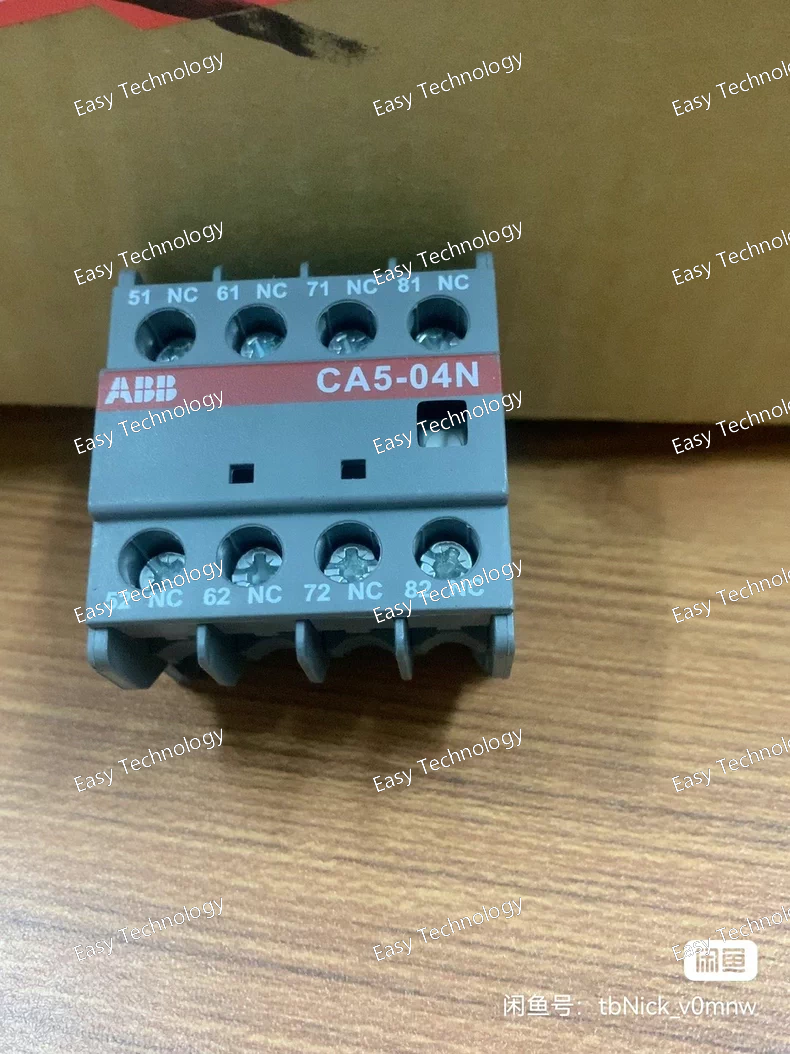
Parameters Category Parameter Specification for CA5-04N General Product Type Digital Multifunction Timer Relay (LED Indication) Series CA5 Series Display None (LED indicators only) DIN Modules 4 modules (approx. 72 mm wide) Power Supply Supply Voltage (Uₛ) 24-240 V AC / 24-240 V DC (Universal) Frequency 50/60 Hz (AC) Power Consumption ≤ 4 VA / 3 W Timing Characteristics Setting Method 3 Rotary Decade Switches (0-9) + 1 Multiplier Switch Time Ranges (Multiplier) x0.1s, x1s, x10s, x1min, x10min, x1h, x10h Setting Range 0.1s to 999h (dependent on multiplier) Accuracy ≤ ±0.5% of set value ± 20 ms Resolution 10 ms Reset Time ≤ 100 ms Input / Control Control Input (Terminal 7) External trigger/start/reset (function depends on mode). Voltage level compatible with Uₛ. Function Selection Rotary Function Switch (A-L, S) Output Output Type Electromechanical Relay Contact Configuration DPDT (2 Changeover) - 2 NO + 2 NC Contact Rating (Resistive) 8 A at 250 V AC 5 A at 30 V DC Minimum Load 10 mA at 5 V DC Electrical Life ≥ 100,000 cycles (rated load) Mechanical Life ≥ 10 million cycles Indicators (LED) Status LEDs Green (PWR): Power On Red (OUT): Output Energized Yellow (TM): Timing in Progress (PLS): Pulse Indicator (in some modes) Terminals Terminal Type Screw clamp terminals Wire Size 0.5 - 2.5 mm² (AWG 20-14) Torque 0.5 - 0.6 Nm Standards & Approvals Compliance Standards IEC/EN 61812-1, UL 508, CSA C22.2 Certifications CE, cULus, CCC Environmental Operating Temperature -20°C to +55°C (no icing) Storage Temperature -40°C to +70°C Altitude Up to 2000 m Pollution Degree PD 2 Protection Degree IP40 (front), IP20 (terminals) Physical & Mounting Mounting 35 mm symmetrical DIN rail (EN 60715) Dimensions (W×H×D) Approx. 72 mm (4 modules) x 90 mm x 64 mm Weight Approx. 0.25 kg
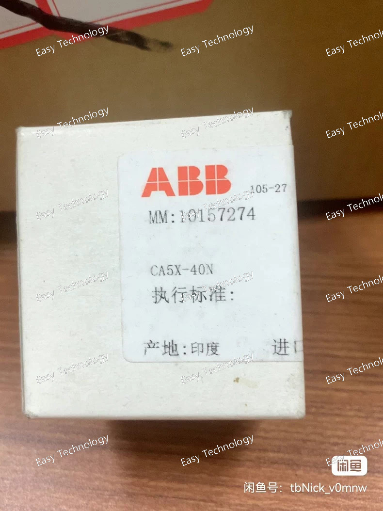
Parameters Category Parameter Specification for CA5X-40N General Product Type Digital Multifunction Timer Relay (LED Indication) Series CA5X Series Display None (LED indicators only) Power Supply Supply Voltage (Uₛ) 24-240 V AC / 24-240 V DC (Universal, auto-sensing) Frequency 50/60 Hz (for AC supply) Power Consumption ≤ 3 VA / 2 W (typical) Timing Characteristics Setting Method Two rotary digit switches (0-99) + Multiplier DIP switch Time Ranges Typically: x0.1s (0.1-9.9s), x1s (1-99s), x10s (10-990s), x1min (1-99min), x10min (10-990min) Accuracy ≤ ±0.5% of set value + 10 ms (typical) Resolution 10 ms Reset Time ≤ 50 ms Input / Control Control Input(s) Integrated with power supply or separate terminal depending on wiring mode (see manual). Function Selection 8-position DIP switch for mode, range, reset behavior, etc. Output Output Type Electromechanical Relay Contact Configuration DPDT (2 Changeover) - 2 NO + 2 NC Contact Rating (Resistive) 8 A at 250 V AC 5 A at 30 V DC Minimum Load 10 mA at 5 V DC Electrical Life ≥ 100,000 cycles (at rated load) Mechanical Life ≥ 10 million cycles Indicators (LED) Status LEDs Green: Power On (PWR) Yellow/Red: Output 1 Active (OUT1) Yellow/Red: Output 2 Active (OUT2) / Timing in Progress Terminals Terminal Type Screw clamp terminals Wire Size 0.5 - 2.5 mm² (AWG 20-14) Torque 0.5 - 0.6 Nm Standards & Approvals Compliance Standards IEC/EN 61812-1, UL 508, CSA C22.2 Certifications CE, cULus, CCC Environmental Operating Temperature -20°C to +55°C (with no icing) Storage Temperature -40°C to +70°C Altitude Up to 2000 m Pollution Degree PD 2 Protection Degree IP40 (front), IP20 (terminals) Physical & Mounting Mounting 35 mm symmetrical DIN rail (EN 60715) Dimensions (W×H×D) Approx. 36 mm (2 modules) x 90 mm x 64 mm Weight Approx. 0.15 kg
 TEL: Grace +86 13600179521
  Mail: info@hongkongeasy.com jilineasyyi@outlook.com
 Q Q:615739355
 ADDRESS:Unit 12, 20th Floor, Good View Commercial Centre, 2-16 Garden Street, Mong Kok, Hong Kong
 whats app


