
Industrial Controller
All product are in stock,guaranteed delivery within 3-7 days.


PRODUCT
PICTURE
BRAND
DESCRIBE
STOCK
DOWNLOAD
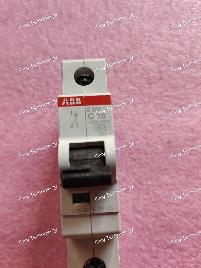
Parameters Category Parameter Specification for S201 C16 General Product Type Single-Pole Miniature Circuit Breaker (MCB) Series System Pro M compact® S200 Poles 1 Pole (1P) Rated Current (In) 16 A Tripping Characteristic "C" Curve Electrical Ratings Rated Operational Voltage (Ue) AC 230/400 V Rated Insulation Voltage (Ui) 500 V AC / 600 V DC Rated Impulse Withstand Voltage (Uimp) 6 kV Rated Frequency 50/60 Hz Breaking Capacity Rated Service Short-Circuit Breaking Capacity (Ics) 6 kA (at 230/400V AC, according to IEC/EN 60898-1) Rated Ultimate Short-Circuit Breaking Capacity (Icu) 6 kA Tripping Characteristics (IEC 60898) Overload (Non-Delayed) 1.13 x In (18.1A): No trip within 1 hour. 1.45 x In (23.2A): Must trip within 1 hour. Magnetic Instantaneous Trip Range 5 x In (80A) to 10 x In (160A). Mechanical & Operational Electrical Life ≥ 10,000 operations (at In) Mechanical Life ≥ 20,000 operations Operation Manual toggle lever. Terminals Terminal Type Cage Clamp (Spring Loaded) Acceptable Conductor Size Solid/Fine-stranded: 1 - 25 mm² With ferrule: 1 - 16 mm² Torque Not required (Spring clamp). Mounting Mounting Standard 35 mm symmetrical DIN rail (EN 60715) Width 1 Module (17.5 mm) Environmental Operating Temperature -25°C to +55°C (Calibrated at +30°C) Storage Temperature -40°C to +70°C Ambient Temperature Compensation Yes (within operating range). Standards & Approvals Primary Compliance IEC/EN 60898-1 (Electrical accessories) Additional Compliance IEC/EN 60947-2 (Circuit-breakers) Certifications CE, CCC, cULus (UL 1077)
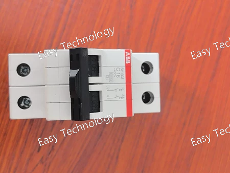
Parameters Category Parameter Specification for SH202-C16 General Product Type Miniature Circuit Breaker (MCB) Series System Pro M compact® S200 Number of Poles 1-Pole + Neutral (1P+N) Rated Current (In) 16 A Tripping Characteristic "C" Curve (General Purpose) Electrical Ratings Rated Voltage (Ue) AC 230/400 V Rated Insulation Voltage (Ui) 500 V Rated Frequency 50/60 Hz Breaking Capacity Rated Service Short-Circuit Breaking Capacity (Ics) 6 kA (at 230/400V AC, per EN/IEC 60898) Rated Ultimate Short-Circuit Breaking Capacity (Icu) 6 kA Tripping Characteristics Overload Protection (Ir) Thermal release. Non-adjustable. Tripping Time for Overload < 1 hour at 1.45 x In (23.2A). Magnetic Trip (Instantaneous) 5 to 10 x In (80A to 160A). Mechanical & Operational Electrical Life ≥ 10,000 cycles (at In) Mechanical Life ≥ 20,000 cycles Operation Manual ON/OFF lever. Terminals Terminal Type Cage Clamp (Spring Loaded) Acceptable Conductor Size Solid/Fine-stranded: 1 - 25 mm² With ferrule: 1 - 16 mm² Torque Not required (Spring clamp). Mounting Mounting Standard 35 mm symmetrical DIN rail (EN 60715) Width 1 Module (18 mm) Environmental Operating Temperature -25°C to +55°C (Calibrated at +30°C) Storage Temperature -40°C to +70°C Ambient Temperature Compensation Yes (from -25°C to +55°C) Standards & Approvals Compliance Standards IEC/EN 60898-1, IEC/EN 60947-2 Certifications CE, CCC, etc. (Market dependent)
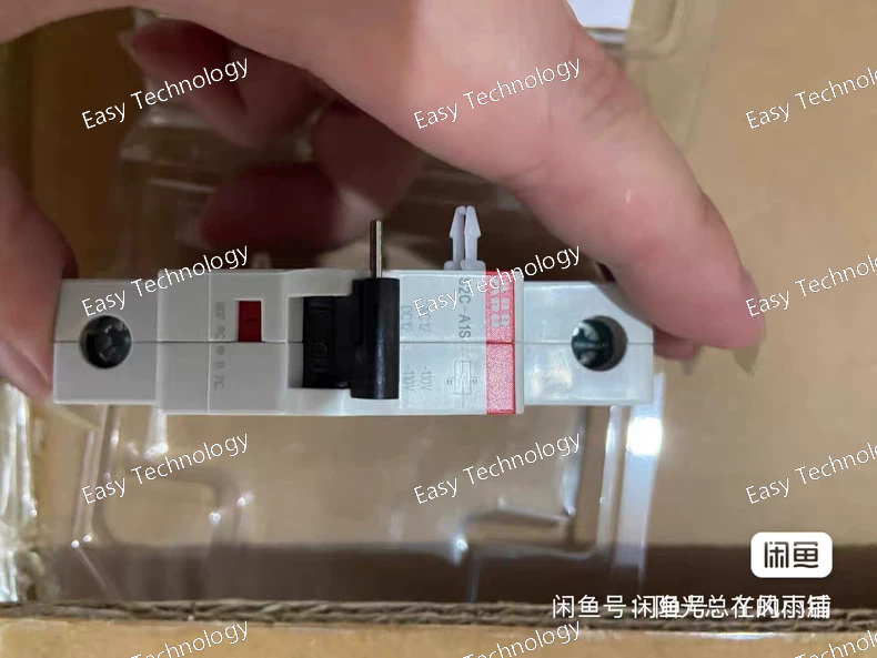
Parameters Category Parameter Specification for S2C-A1S General Type Low-Power, Plug-in Signal Relay (Ice-Cube Type) Contact Configuration SPDT (1 Form C) – 1 Common (C), 1 NO, 1 NC. Mounting Plug-in to a compatible 8-pin or 11-pin square base socket. Coil Data Rated Coil Voltage (Uc) Universal: e.g., 24 V AC/DC (A common rating. Must verify actual marking). Operational Voltage Range AC: 0.85 to 1.1 x Uc; DC: 0.7 to 1.3 x Uc. Coil Power Consumption Low Power: ~0.36 W DC / ~0.9 VA AC (typical for 24V). Coil Resistance Approx. 1600 Ω (for 24V DC coil, typical). Contact Data Contact Material Fine Silver or Silver Alloy. Max. Switching Voltage 250 V AC / 125 V DC. Max. Switching Current 5 A (at 250V AC, resistive). Max. Switching Power AC-15: 750 VA; DC-13: 60 W. Minimum Load 10 mA at 5 V DC. Performance Electrical Life > 100,000 operations (at rated load). Mechanical Life > 10 million operations. Operate/Release Time < 10 ms / < 5 ms (typical). Indication Status Indicator Integrated LED (Red, typical). Terminals Connection Plug-in pins. Wiring connects to the screw terminals of the mounting socket. Environmental Operating Temperature -40°C to +70°C. Storage Temperature -55°C to +85°C. Protection Degree IP40 (with cover). Standards Compliance IEC/EN 61810-1, IEC/EN 60947-5-1. Approvals CE, cULus.
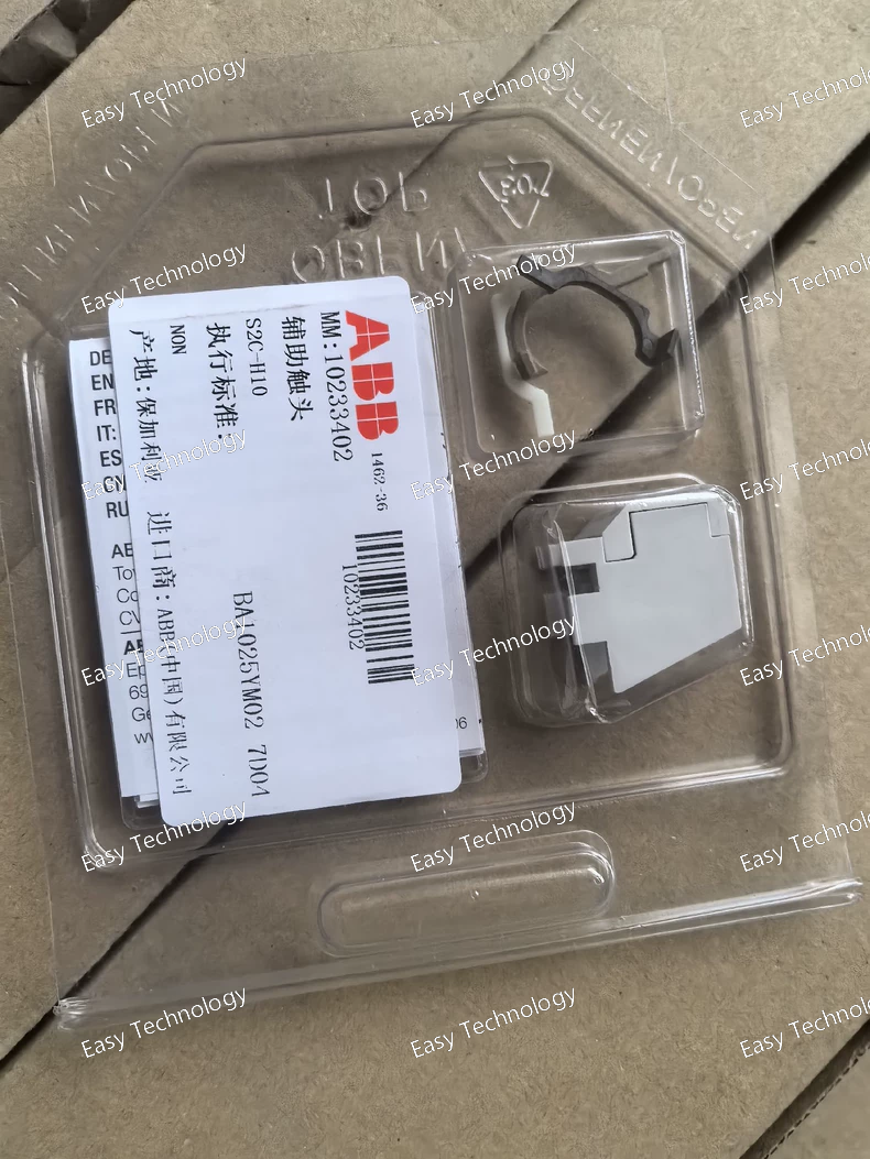
Parameters Category Parameter Specification for S2C-H10 General Type General Purpose, Plug-in "Ice Cube" Relay Contact Configuration SPDT (1 Form C) – 1 changeover contact. Mounting Plug-in to a compatible 8-pin or 11-pin square base socket (e.g., ABB SA series). Coil Data Rated Coil Voltage (Uc) 110 V AC, 50/60 Hz (Most common interpretation of "H10"). Operational Voltage Range 0.85 to 1.1 x Uc (Typically ~85V to 121V AC). Coil Power Consumption Pick-up: ~4.5 VA; Holding: ~2.0 VA (typical). Coil Impedance Approx. 2.7 kΩ (at 50Hz, typical). Contact Data Contact Material Fine Silver or Silver Alloy. Max. Switching Voltage 250 V AC / 30 V DC. Max. Switching Current (Resistive) 10 A (at 250V AC). Max. Switching Power AC-15: 1500 VA (cos φ=0.3); DC-13: 90 W (L/R=40ms). Minimum Switching Load 100 mA at 5 V DC (for reliable contact operation). Performance Electrical Life > 100,000 operations (at rated load). Mechanical Life > 10 million operations. Operate/Release Time Approx. 15 ms / 10 ms (typical for AC coil). Indication Status Indicator Mechanical flag (visible under transparent cover). Terminals Connection Plug-in pins. Wiring is done to the screw terminals of the mounting socket. Environmental Operating Temperature -40°C to +70°C. Storage Temperature -55°C to +85°C. Protection Degree IP40 (with cover, as mounted). Standards Compliance IEC/EN 61810-1, IEC/EN 60947-5-1. Approvals CE, cULus, CCC.
Parameters Category Parameter Specification for S2C-H11R General Type General Purpose, Plug-in "Ice Cube" Relay Contact Configuration SPDT (1 Form C) – 1 changeover contact (1 Common, 1 NO, 1 NC). Mounting Plug-in to a compatible 8-pin or 11-pin square base socket. Coil Data Rated Coil Voltage (Uc) 24 V DC (Most common interpretation of "H11R"). Always verify with datasheet. Operational Voltage Range 0.7 to 1.3 x Uc (Typically ~17V to 31V DC). Coil Resistance Approx. 720 Ω (Typical for 24V DC, 330mW coil). Nominal Coil Power 0.33 W (at 24V DC). Contact Data Contact Material Fine Silver or Silver Alloy. Max. Switching Voltage 250 V AC / 30 V DC. Max. Switching Current 10 A (at 250V AC, resistive). Max. Switching Power AC-15: 1500 VA (at cos φ=0.3); DC-13: 90 W (at L/R=40ms). Minimum Load 10 mA at 5 V DC (for reliable contact cleaning). Performance Electrical Life > 100,000 operations (at rated load). Mechanical Life > 10 million operations. Operate/Release Time Approx. 10 ms / 5 ms (typical). Indication Status Indicator Integrated LED (Red, typically). Terminals Connection Plug-in pins. Wires connect to screw terminals on the mounting socket. Environmental Operating Temperature -40°C to +70°C. Storage Temperature -55°C to +85°C. Protection Degree IP40 (with cover, as mounted). Standards Compliance IEC/EN 61810-1, IEC/EN 60947-5-1. Approvals CE, cULus.
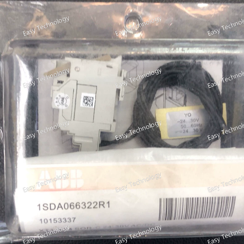
Parameters Category Parameter Specification / Interpretation for 1SDA066322R1 General Functional Model REF615 Feeder Protection Relay Product Line Relion® 615 Series Hardware Level Likely "C" (Control) or "E" (Enhancement) Level Power Supply Operational Voltage Common: 110-250 V DC (Substation battery) or 110-230 V AC. Analog Inputs Rated Current (In) 1 A or 5 A (Defined by order code). Thermal Withstand Continuous: 4 x In; 1s: 100 x In. Voltage Inputs 100-120V or 190-230V line-to-neutral (via VTs). Digital I/O Binary Inputs (BI) Typically 16 (configurable in groups). Output Relays Typically 6 Trip/Close (PO) + 8 Signal (BO). Human-Machine Interface Display Graphical LCD with backlight. Local Control Keypad for navigation and operation. Communication Primary Protocol IEC 61850-8-1 (MMS & GOOSE) Secondary Protocols IEC 60870-5-103, Modbus RTU. (DNP3 may not be included in this variant). Physical Ports 2 x Ethernet (RJ45 + Optical), 2 x RS485. Protection Functions Core ANSI Functions 67/67N (Dir. OC/EF), 50/51/51N, 27/59, 79 (Recloser), 49 (Thermal), 81U/f, 50BF (CB Fail). Metering & Monitoring Measurements I, V, P, Q, S, PF, F, Energy – Class 0.5/1.0. Power Quality Harmonics, unbalance. Disturbance Recorder Oscillographic (≥ 8 analog channels). Event Log (SOE) ≥ 1024 time-tagged events. Logic Programmability CFC (IEC 61131-3) & Sequence Control. Environmental Operating Temperature -25°C to +70°C (standard). Protection Degree IP40/IP52 (panel mounted). Standards Compliance IEC 60255, IEC 61850, IEEE C37.90, IEC 61000-4 (EMC).
Parameters Category Parameter Specification / Interpretation for 1SDA066325R1 General Functional Model REF615 Feeder Protection Relay Product Line Relion® 615 Series Hardware Level Likely "E" (Enhancement) Level Order Code Type Configured Spare Part / Complete Unit Power Supply Operational Voltage Likely 110-250 V DC (Common for substation battery) or 110-230 V AC. Analog Inputs Rated Current (In) 1 A or 5 A (secondary, defined by order code). Continuous Thermal Withstand 4 x In Voltage Inputs (VTs) 100-120V or 190-230V line-to-neutral. Digital I/O Binary Inputs (BI) Typically 16 (configurable in voltage groups). Output Relays Typically 6 Trip/Close (PO) + 8 Signal (BO). Human-Machine Interface Display High-resolution Graphical LCD. Local Control Keypad with navigation buttons. Communication Primary Protocol IEC 61850-8-1 (MMS & GOOSE) Included Protocols DNP3 (TCP/IP & Serial), Modbus RTU, IEC 60870-5-103. Physical Ports 2 x Ethernet (RJ45 + Optical SFP), 2 x RS485. Protection Functions Core ANSI Functions 67/67N (Dir. OC/EF), 50/51/51N, 27/59, 79 (Recloser), 49 (Thermal), 81U/81O, 50BF. Metering Measurements I, V, P, Q, S, PF, F, Energy (Wh, varh) – Class 0.5. Power Quality Harmonics (up to 15th), THD, unbalance. Recording Disturbance Recorder Oscillographic (≥ 8 analog channels, 128 samples/cycle). Event Log (SOE) ≥ 1024 time-tagged events. Trip Log Last 256 faults with details. Logic & Control Programmability CFC (IEC 61131-3) & Sequence Control. Environmental Operating Temperature -25°C to +70°C (standard). Protection Degree IP40/IP52 (panel mounted). Standards Compliance IEC 60255, IEC 61850, IEEE C37.90, IEC 61000-4 (EMC).
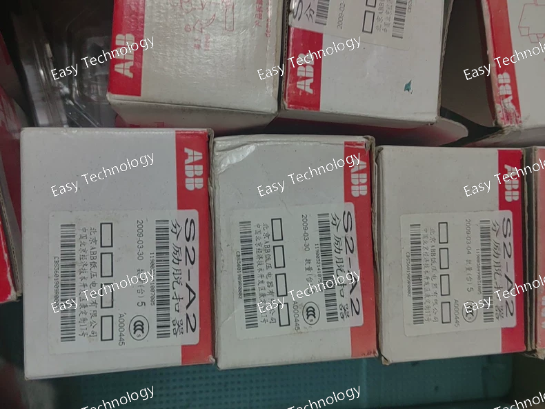
Parameters Category Parameter Specification for S2-A2 110-415V General Type General Purpose Plug-in Relay, 8-pin (Octal Base) Contact Configuration DPDT (2 Form C) – 2 changeover contact sets. Mounting 8-pin Octal Plug-in Base (e.g., PK-0 socket). Can be panel-mounted with socket or DIN-rail mounted with adapter. Coil Data Rated Coil Voltage (Uc) AC 110-415 V, 50/60 Hz (Universal range). Operational Voltage Range 0.8 to 1.1 x Uc (Typically 85-460V AC). Coil Power Consumption Pick-up: ~4.5 VA; Holding: ~2.5 VA (typical values). Thermal Dissipation Approx. 1.5 W. Contact Data Contact Material Fine Silver or Silver Alloy. Max. Switching Voltage 250 V AC / 30 V DC. Max. Switching Current (Resistive) 10 A (at 250V AC). Max. Switching Power AC-15: 1500 VA (at cos φ=0.3); DC-13: 90 W (at L/R=40ms). Minimum Switching Load 100 mA at 5 V DC (for reliable contact wiping). Performance Electrical Life > 100,000 operations (at rated load). Mechanical Life > 10 million operations. Operate/Release Time Approx. 15 ms / 10 ms (typical). Max. Switching Frequency ~3600 operations/hour (mechanical). Indication Status Indicator Mechanical flag (visible through cover). Terminals Connection (via Socket) Screw clamp terminals on the octal socket. Wire Size Up to 2.5 mm². Environmental Operating Temperature -40°C to +60°C. Storage Temperature -55°C to +85°C. Protection Degree IP40 (with cover, as mounted). IP20 (terminals). Vibration/Shock Resistance Suitable for standard industrial environments. Standards Compliance IEC/EN 61810-1, IEC/EN 60947-5-1. Approvals CE, cULus, CCC.
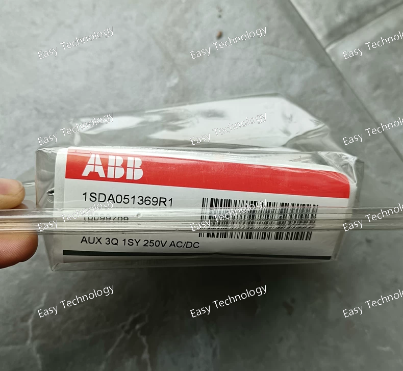
Parameters Category Parameter Specification / Interpretation for 1SDA051369R1 General Functional Model REF615 / RET615 Feeder or Transformer Protection Relay Product Line Relion® 615 Series Hardware Level "C" or "E" Level (Control/Enhancement - inferred from capabilities) Power Supply Operational Voltage Likely 110-250 V DC or 110-230 V AC (Order code specific). Analog Inputs Rated Current (In) 1 A or 5 A (secondary, defined by order code). Thermal Withstand Continuous: 4 x In; 1s: 100 x In. Voltage Inputs 100-120V or 190-230V line-to-neutral (via VT). Digital I/O Binary Inputs (BI) Typically 16 (configurable voltage groups). Output Relays Typically 6-8 Trip/Close relays (PO) + 8 Signal relays (BO). HMI Display Graphical LCD (high-resolution). Interface Front keypad, navigation buttons. Communication Primary Protocol IEC 61850-8-1 (Edition 2) Included Protocols DNP3 (TCP/IP & Serial), Modbus RTU, IEC 60870-5-103. Physical Ports 2 x Ethernet (RJ45 + ST optical), 2 x RS485. Protection Functions Core ANSI Functions 50/51/67 (Phase OC), 50N/51N/67N (Earth Fault), 27/59 (Voltage), 79 (Recloser), 49 (Thermal), 50BF (CB Fail). Metering Measurements I, V, P, Q, S, PF, F, Energy (Wh, varh) – Class 0.5/1.0. Power Quality Harmonics (THD), unbalance. Recording Disturbance Recorder Oscillographic (≥ 8 analog channels, 128 samples/cycle). Event Log (SOE) ≥ 1024 time-tagged events. Logic Programmability CFC (IEC 61131-3) & Sequence Control. Environmental Operating Temperature -25°C to +70°C (standard). Protection Degree IP40/IP52 (panel mounted). Standards Compliance IEC 60255, IEC 61850, IEEE C37.90, IEC 61000-4 (EMC).
Parameters Category Parameter Specification / Interpretation for 5SHX2645L0004 General Device Type Asymmetric, Non-Punch-Through (NPT), Press-Pack IGCT Series 5SHX 26 (Asymmetric IGCT Series) Blocking Voltage Class 4500 V (Indicated by "2645" – 26xx series, 45 = 4.5kV) Voltage Ratings Repetitive Peak Off-State Voltage (VDRM) 4500 V Non-Repetitive Peak Off-State Voltage (VDSM) ~5000 V Current Ratings Average On-State Current (ITAV) @ Tc=85°C ~2000 - 2800 A (Highly dependent on cooling, frequency, and waveform) RMS On-State Current (ITRMS) ~3000 - 4000 A Peak Controllable Current (ITGQM) ~4000 - 5000 A Non-Rep. Surge Current (ITSM) ~30 - 40 kA (for 10 ms half-sine) Switching Characteristics Turn-On Time (ton) 1 - 3 µs (with gate unit) Turn-Off Time (toff) 15 - 25 µs (including storage time) Turn-Off Safe Operating Area (RBSOA) Excellent, snubberless operation possible. Critical Rate of Rise of Off-State Voltage (dv/dt) > 2000 V/µs Thermal & Mechanical Junction Operating Temperature (Tvj) -40°C to +125°C Clamping Force Critical! Typically 30 - 40 kN. Must be applied uniformly with calibrated tooling. Mounting Double-sided press-fit between liquid-cooled heatsinks. Cooling Required Forced liquid cooling (deionized water/glycol) is standard. Gate Drive Gate Unit Requirement ABSOLUTELY REQUIRED. Must be driven by a dedicated, matched ABB IGCT Gate Unit (e.g., 5STP 18L4200 or similar) which provides the very high peak gate current (>1000 A) for hard-driven turn-on and precise turn-off. Companion Diode Required Series Diode An asymmetric press-pack diode (e.g., ABB 5SDF 10H4503) must be connected in series with this IGCT to block reverse voltage in an inverter leg. Typical Application Circuit Converter Topology 3-Level Neutral Point Clamped (NPC) / ANPC VSC, 2-Level VSC with series connection. System Examples ACS 6080 Drive, PCS 8000 STATCOM, HVDC Light Valve Submodule.
Parameters Category Parameter Specification for 07KT97F1 General Module Type Universal, Multi-Range Analog Input Module Compatible System ABB Freelance DCS, AC 700F/800F PLC, S800 I/O System Form Factor S800 I/O Single-Width Module Input Channels Number of Channels 8 channels (typical for this series). Channel Isolation Individual channel-to-channel and channel-to-system isolation. Analog Input Signals Configurable Types Voltage: 0-10V, ±10V Current: 0-20mA, 4-20mA (with 2-wire transmitter supply) Resistance: For RTDs (Pt100, Pt1000) Thermocouple: Types J, K, T, E, N, R, S, B Input Impedance Voltage: > 1 MΩ; Current: ≤ 250 Ω (internal shunt). Transmitter Supply 24 V DC (per channel, for 2-wire transmitters). Conversion & Performance Resolution 16-bit (or 15-bit + sign). Conversion Time Per channel: Typically 20 - 50 ms for all 8 channels (scan rate). Accuracy Typically ±0.1% of full scale (at 25°C, for voltage/current). RTD: ±0.2°C; TC: ±1°C (typical). Filtering Software-configurable digital filtering. Diagnostics & Alarms Diagnostic Functions Wire break (open circuit), short circuit, underrange, overrange, module fault. Status Indication LED per channel (green/red) for communication and fault status. Electrical & Environmental Backplane Power +5V DC from the S800 power supply. Field-Side Power 24V DC supplied to transmitters (if enabled). Isolation Voltage Channel-to-Bus: Typically 500 V AC (1 min). Operating Temperature 0°C to +60°C Storage Temperature -40°C to +85°C Relative Humidity 5% to 95%, non-condensing. Communication Bus Interface Profibus DP or Foundation Fieldbus (depending on the connected fieldbus module, e.g., CI871). Software Configuration Tool ABB Control Builder F (CBF) or Freelance Engineering.
Parameters Category Parameter Specification for 5SHY4045L0003 General Device Type Reverse-Conducting, Asymmetric, Press-Pack IGCT (Integrated Gate-Commutated Thyristor) with Integrated Anti-Parallel Diode Series 5SHY 40 Voltage Ratings Repetitive Peak Off-State Voltage (VDRM) 4500 V (Primary voltage class indicated by "4045") Non-Repetitive Peak Off-State Voltage (VDSM) ~5000 V Gate-Cathode Reverse Voltage ~20 V Current Ratings Average On-State Current (ITAV) ~2000 - 3000 A (highly dependent on cooling and frequency) RMS On-State Current (ITRMS) ~3000 - 4500 A Non-Repetitive Peak Surge Current (ITSM) ~30 - 50 kA (for 10 ms sine wave) Peak Controllable Current (ITGQM) ~4000 - 6000 A Switching Characteristics Turn-On Time (ton) < 5 µs (typical, with gate unit) Turn-Off Time (toff) ~15 - 25 µs (including storage time) Critical Rate of Rise of Off-State Voltage (dv/dt) > 1000 V/µs Integrated Diode Reverse Recovery Charge (Qrr) ~5 - 10 mC (at high di/dt) Thermal & Mechanical Junction Operating Temperature (Tvjop) -40°C to +125°C Storage Temperature -40°C to +125°C Clamping Force Critical. Typically 25 - 35 kN (must be applied via calibrated tool). Housing Material Ceramic-metal (Press-Pack) Cooling Double-sided, liquid or forced air cooling required. Gate Drive Gate Unit Requirement Must be driven by a dedicated, matched ABB IGCT Gate Unit (e.g., 5STP... series) which provides the very high peak gate current (>>100A) required for hard switching. Typical Application Used In Converters 3-Level NPC (Neutral Point Clamped) Inverter, 3-Level Active Front End. System Examples ABB ACS 6000 Drive, PCS 6000 STATCOM, HVDC Light Valve.
 TEL: Grace +86 13600179521
  Mail: info@hongkongeasy.com jilineasyyi@outlook.com
 Q Q:615739355
 ADDRESS:Unit 12, 20th Floor, Good View Commercial Centre, 2-16 Garden Street, Mong Kok, Hong Kong
 whats app


