
Industrial Controller
All product are in stock,guaranteed delivery within 3-7 days.


PRODUCT
PICTURE
BRAND
DESCRIBE
STOCK
DOWNLOAD
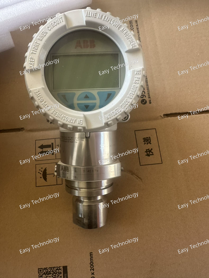
Parameters Category Parameter Specification for 266HSHWSBA1 General Model Series 2600T Series (FMT - Flow Multivariable Transmitter) Type Smart 4-20 mA/HART Multi-Variable Flow Transmitter Measured Variables Differential Pressure (ΔP), Static Pressure (Ps), Temperature (T). Measurement Performance ΔP Span Limits Wide range, e.g., from 0.1 kPa to 3 MPa (model dependent). Static Pressure (Ps) Range e.g., 0 to 16 MPa (2320 psi) (model dependent). Temperature (T) Range e.g., -40°C to +125°C (via integrated RTD). Reference Accuracy (Flow) Typically ±0.15% of reading (with all inputs). Long-Term Stability ±0.1% of URL per year (typical). Computation & Output Flow Calculation Mass or Volumetric. Compensates for Ps & T. Fluid Database Pre-loaded with common gas/steam properties. Primary Element Support Orifice, Venturi, Nozzle, Wedge, etc. (ISO/AGA). Analog Output 4-20 mA, HART 5/6/7. PV = Flow. Digital Output HART. SV = Ps, TV = T. Electrical Supply Voltage 10.5 to 42 V DC (two-wire). Communication HART Protocol (Bell 202 FSK). Process Connections & Materials ΔP Ports 1/4" NPT or G1/2" female (High & Low side). Ps & T Port 1/2" NPT or similar (integrated in process flange). Wetted Parts 316L SST, Hastelloy C-276 options. Mechanical & Environmental Housing Aluminum or Stainless Steel. Protection Degree IP66 / IP67 / NEMA 4X Process Temp. (Flange) -40°C to +120°C Ambient Temp. -40°C to +85°C Certifications Explosion Protection ATEX / IECEx: Ex ia IIC T4/T6 Ga & Ex d IIC T4/T6 Gb options. Safety Integrity Level SIL 2/3 capable.
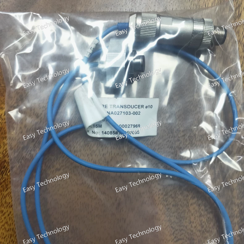
Parameters Category Parameter Specification / Interpretation for 3HNA027103-002 General Part Type Robot Axis Motor Brake Release Unit / Module Compatible Robot Series IRB 6600 (Primary), potentially other large ABB robots. Controlled Axes Likely Axes 1, 2, and 3 (or a similar primary axis group). Electrical Input Control Input Signals Two independent, safe digital signals from the robot controller's safety board (e.g., BR1 and BR2). Input Voltage (Logic) Typically 24 V DC (sourced from the drive module's internal supply). Electrical Output Output to Brake Coils High Voltage DC: Commonly 90 V DC (for the specific motor brakes used in IRB 6600). Output Current Inrush Current: Several Amperes per brake. Holding Current: Lower, regulated current. Number of Output Channels 3 channels (one for each brake coil of axes 1, 2, and 3). Safety & Monitoring Safety Standard Designed to meet Performance Level d (PLd) / Category 3 per ISO 13849-1, as part of the robot's overall safety system. Fault Detection Monitors for open circuit, short circuit, and feedback mismatch on the brake release circuits. Fail-Safe State De-energized (Brakes ENGAGED/LOCKED). Physical & Integration Form Factor Printed Circuit Board (PCB) assembly designed to plug into or mount within a specific drive module chassis. Mounting Location Inside the robot's Drive Module (e.g., a module in the IRC5 controller cabinet). Environmental Operating Temperature 0°C to +55°C (Standard for electronics inside controller cabinet). Storage Temperature -25°C to +70°C
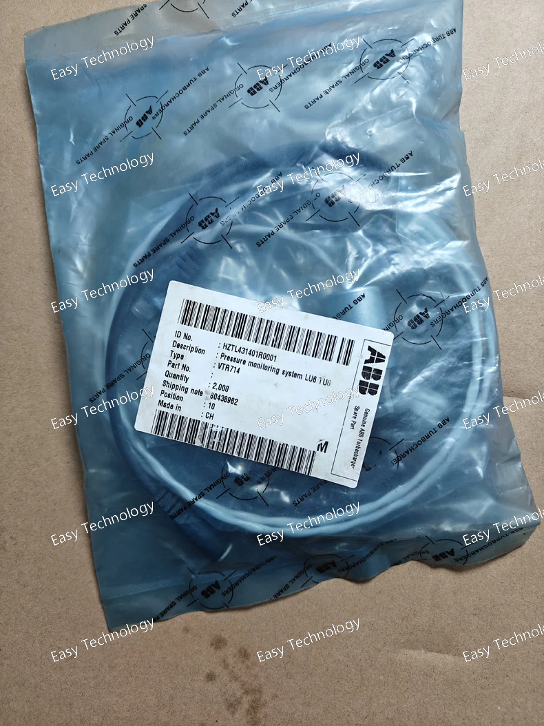
Parameters Category Parameter Typical Specification / Interpretation for VTR714 General Type Truck-Mounted, Air-Insulated, Vacuum Circuit Breaker Mounting Withdrawable, for UniGear ZS1 or similar metal-clad switchgear. Rated Values Rated Voltage (Ur) 7.2 kV, 12 kV, or 15 kV (System dependent). Rated Frequency 50 Hz / 60 Hz Rated Normal Current (Ir) Likely in the range of 1250A, 1600A, 2000A, 2500A, or 3150A. ("714" may indicate a 2000A or 2500A frame). Rated Short-Time Withstand Current (Ik) 25 kA or 31.5 kA for 3 seconds (Typical). Breaking Capacity Rated Short-Circuit Breaking Current (Isc) 25 kA or 31.5 kA (Symmetrical RMS). Rated Making Current 2.5 x Isc (Peak) Interrupting Medium Arc Extinction Medium High Vacuum Number of Interrupters per Pole 1 Mechanical Operating Mechanism Spring-operated stored energy mechanism. Motor-charged, with manual charging option. Closing Time ~60 - 100 ms Opening Time ~30 - 60 ms (Including relay time). Mechanical Endurance 10,000 - 20,000 operations Control & Auxiliary Rated Control Supply Voltage AC/DC: 110V, 125V, 220V, 250V (Order specific). Auxiliary Contacts Multiple NO/NC contacts for signaling and interlocking. Physical Cooling (for high-current variants) Natural convection (air) or forced liquid cooling for terminals/bushings. Weight Approx. 250 - 400 kg (Highly dependent on current rating). Standards Compliance IEC 62271-100, IEC 62271-1, ANSI/IEEE C37.04, C37.06.
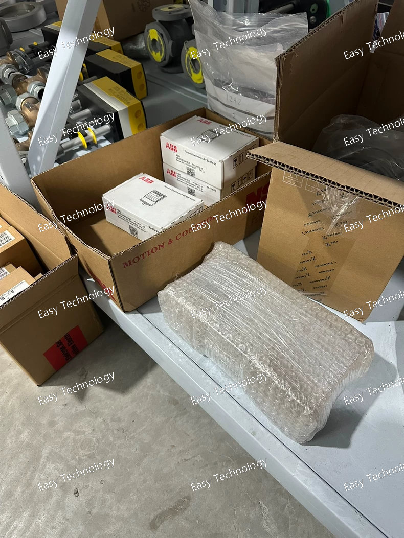
Parameters Category Parameter Specification for PFTL101A-2KN General Model Series 2600T Series Type Smart, Low-Range Differential Pressure Transmitter Output Signal 4-20 mA DC, two-wire, with HART digital communication. Measurement Performance Measured Variable Differential Pressure (dP) Span Limits (Typical) Minimum: 0.1 kPa (1 mbar, ~0.4 inH₂O) Maximum: 40 kPa (400 mbar, ~6 psi) Reference Accuracy ±0.075% of calibrated span (typical for this class). Long-Term Stability ±0.1% of URL per year (typical). Turndown Ratio Up to 100:1 (programmable). Electrical Supply Voltage 10.5 to 45 V DC (standard for two-wire loop). Load Limit R_L ≤ (Vs - 10.5V) / 0.022 A (Ω) Communication HART Protocol (Bell 202 FSK). Process Connections & Materials Wetted Parts Isolating Diaphragms: 316L SST Process Flanges: 316 SST Fill Fluid Silicone oil or Inert Fluorocarbon (for aggressive media). Pressure Ports 1/4" NPT female or G1/2" (common). Static Pressure Limit Typically 16 MPa (2300 psi) for flange. Overpressure Limit Up to full static pressure rating without damage. Mechanical & Environmental Housing Material Aluminum alloy with epoxy paint or stainless steel. Protection Degree IP66 / IP67 / NEMA 4X Display (Optional) Local indicator (LCD) available. Process Temperature Limits -40°C to +120°C (for standard fill fluid). Ambient Temperature Limits -40°C to +85°C Certifications Explosion Protection ATEX / IECEx: Ex ia IIC T4/T6 Ga (Intrinsic Safety) & Ex d IIC T4/T6 Gb (Flameproof) options. Other CE, SIL 2/3 (capable).
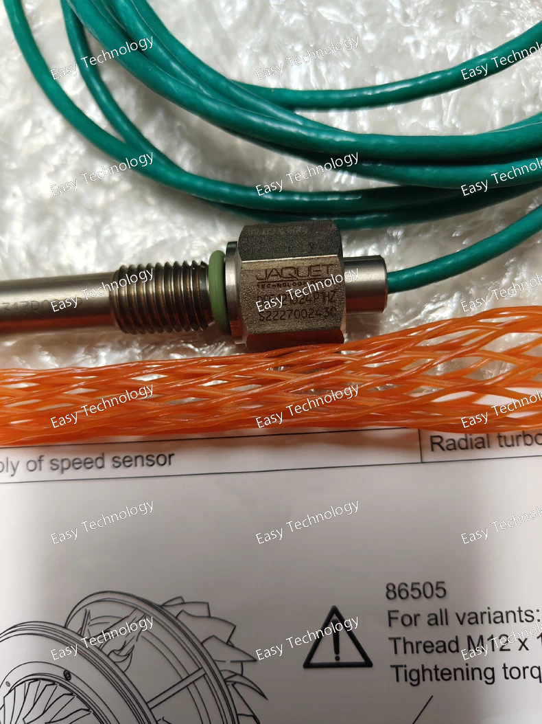
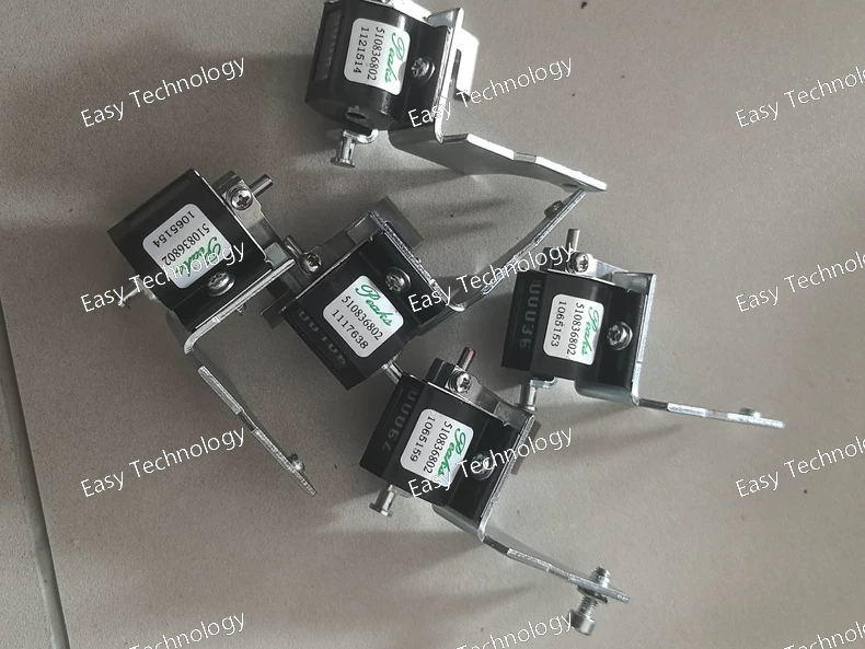
Parameters Category Parameter Specification for DSE1210.24 P1HZ General Model Series DSE 1000 Series Controller Type Multifunction Generator Control Module System Frequency 50 Hz (P1HZ variant) Power Supply Operating Voltage 10 to 35 V DC (Nominal 12/24V) Power Consumption < 5 W (Typical) Engine Monitoring & Protection Engine Speed Sensing Magnetic pickup or alternator W terminal (phase). Analog Inputs 6 dedicated: For Oil Pressure, Coolant Temp, Fuel Level, etc. (configurable as 0-5V, 4-20mA, potentiometer). Engine Protection Shutdowns Configurable for Low Oil Pressure, High Coolant Temp, Overspeed, Underspeed, Crank Overheat, Fail to Start. Generator (Alternator) Monitoring & Protection AC Voltage Inputs 3-Phase + Neutral measurement. AC Current Inputs 3-Phase via external 5A Current Transformers (CTs). Electrical Protection Configurable Over/Under Voltage, Over/Under Frequency, Overcurrent. Control & I/O Digital Inputs 8 programmable (e.g., Mains Available, Emergency Stop, Remote Start). Relay Outputs 6 programmable (e.g., Crank, Fuel Solenoid, Mains Contactor, Generator Contactor, Alarm). Pre-Start/Post-Stop Sequences Fully programmable with glow plug control, etc. User Interface Display 128 x 64 pixel backlit LCD Keypad 6 tactile buttons Communication Ports 1 x RS-232 (for PC config), 1 x RS-485 (for Modbus RTU network). Protocol Modbus RTU (Slave) Environmental Operating Temperature -30°C to +70°C Storage Temperature -40°C to +85°C Protection Degree IP54 (Front panel) Certifications Marine DNV-GL, ABS, BV, LR, RINA (Typically)
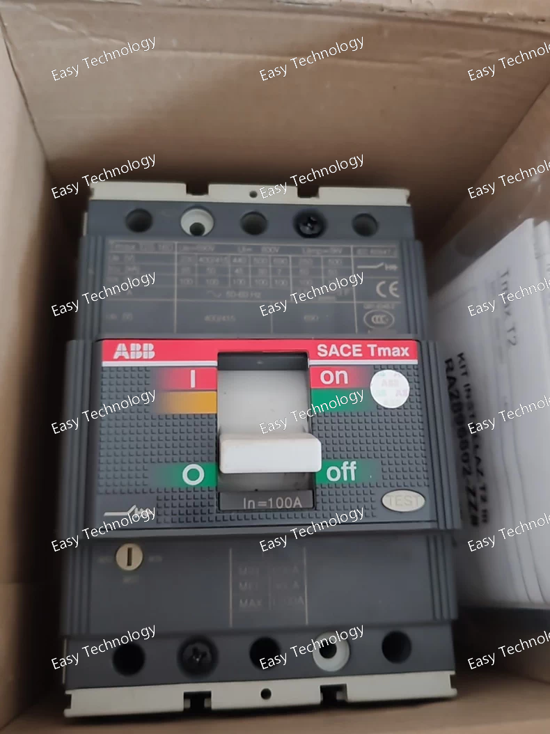
Parameters Category Parameter Specification for T2S160 MA100 General Product Series Tmax T2 Frame Current (Iu) 160 A Number of Poles 3 Poles Trip Unit Type Micrologic 2.0 MA (Metering & Protection) Rated Operational Values Rated Insulation Voltage (Ui) 690 V AC Rated Operational Voltage (Ue) 415 V AC (50/60 Hz) Breaking Capacities Ultimate Breaking Capacity (Icu) at 415V 50 kA (According to IEC 60947-2) Service Breaking Capacity (Ics) at 415V 50 kA (100% Icu for this series) Trip Unit Settings (Micrologic MA) Long-Time Protection (L) Adjustable Ir: (0.4 - 1.0) x In (64A - 160A). Short-Time Protection (S) Adjustable Isd: (1.5 - 10) x Ir. Adjustable Delay Tsd. Instantaneous Protection (I) Adjustable Ii: (1.5 - 15) x In (240A - 2400A) or OFF. Ground-Fault Protection (G) Adjustable Ig: (0.2 - 1.0) x In (32A - 160A). Adjustable Delay Tg. Metering Functions (MA Trip Unit) Measured Values Current (per phase, neutral), Voltage (L-L, L-N), Frequency, Active/Reactive/Apparent Power (P/Q/S), Power Factor, Energy (kWh, kvarh), Demand. Accuracy Class Class 1 (per IEC 61557-12) Display Backlit LCD Communication Platform Ready for plug-in communication modules (e.g., for Modbus, Profibus DP, Ethernet). Mechanical Electrical Durability 10,000 operations Mechanical Durability 25,000 operations Terminals Rated Torque Front/Rear: Typically 15 - 20 Nm for main terminals. Environmental Operating Temperature -25°C to +70°C (Trip unit: -20°C to +70°C) Standards & Approvals Compliance IEC/EN 60947-2, UL 489 Certifications CE, cULus, CCC
Parameters Category Parameter Typical Specification for E-Series General Product Type Modular LED Signal Tower / Stack Light Modularity Stackable modules: E1 (Top segment) to E5/E6 (Base/Sounder). Optical Module Light Source High-Intensity LEDs Standard Colors Red, Yellow (Amber), Green, Blue, White, Clear. Light Patterns Steady, Flashing, Strobe (pattern often controlled by external flasher relay or internal electronics). Light Intensity High luminous output, visible from long distances in bright ambient light. Acoustic Module (Optional) Sound Output Horn, Buzzer, or Siren. Sound Patterns Continuous, Intermittent (beeping), warble. Sound Pressure Level Adjustable, typically 75 - 105 dB(A) at 1 meter. Tone Frequencies Selectable (e.g., 2-4 different tones). Electrical Operating Voltage Universal AC/DC: e.g., 24V DC/AC, 48V DC, 110V AC, 230V AC. Power Consumption per Module Low (LED): Typically 1 - 3 W per light segment. Control Input Dry contact (relay) or voltage signal. Mechanical & Environmental Housing Material Polycarbonate (PC) or similar high-impact plastic. Protection Degree (IP) IP65 (Standard), IP67/IP69K options available. Operating Temperature -25°C to +55°C (or wider). Ambient Light Immunity Designed for high ambient light (up to 20,000 Lux). Mounting M30 x 1.5 threaded base, magnetic base, or bracket. Connections Wiring Pre-assembled cable with connector between modules, or terminal blocks in base. Cable Entry PG9 or M16 gland at the base. Standards & Approvals Compliance IEC/EN 60529 (IP), IEC/EN 60947-5-2 (Proximity switches), CE, cULus.
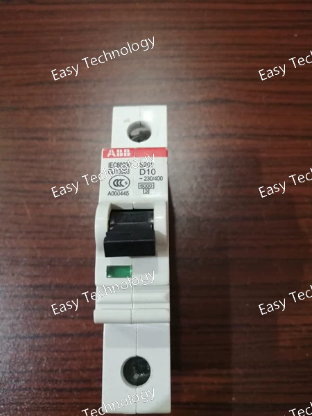
Parameters Category Parameter Specification for S261-D10 General Product Type Single-Pole Miniature Circuit Breaker (MCB) Series System Pro M compact® S200 Poles 1 Pole (1P) Rated Current (In) 10 A Tripping Characteristic "D" Curve Electrical Ratings Rated Operational Voltage (Ue) AC 230/400 V Rated Insulation Voltage (Ui) 500 V Rated Frequency 50/60 Hz Breaking Capacity Rated Service Short-Circuit Breaking Capacity (Ics) 6 kA (at 230/400V AC, per IEC/EN 60898-1) Rated Ultimate Short-Circuit Breaking Capacity (Icu) 6 kA Tripping Characteristics (IEC 60898) Overload (Thermal) 1.13 x In (11.3A): No trip within 1 hour. 1.45 x In (14.5A): Must trip within 1 hour. Magnetic Instantaneous Trip Range 10 x In (100A) to 20 x In (200A). Mechanical & Operational Electrical Life ≥ 10,000 operations (at In) Mechanical Life ≥ 20,000 operations Operation Manual toggle lever. Terminals Terminal Type Cage Clamp (Spring Loaded) Acceptable Conductor Size Solid/Fine-stranded: 1 - 25 mm² With ferrule: 1 - 16 mm² Mounting Mounting Standard 35 mm symmetrical DIN rail (EN 60715) Width 1 Module (17.5 mm) Environmental Operating Temperature -25°C to +55°C (Calibrated at +30°C) Storage Temperature -40°C to +70°C Standards & Approvals Primary Compliance IEC/EN 60898-1 Certifications CE, CCC, etc.
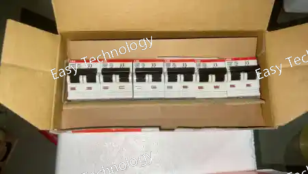
Parameters Category Parameter Specification for S262-C20 General Product Type 2-Pole Miniature Circuit Breaker (MCB) Series System Pro M compact® S200 Poles 2 Poles (2P) Rated Current (In) 20 A per pole Tripping Characteristic "C" Curve (per pole) Electrical Ratings Rated Operational Voltage (Ue) AC 230/400 V (Phase-to-Phase: 400V) Rated Insulation Voltage (Ui) 500 V Rated Frequency 50/60 Hz Breaking Capacity Rated Service Short-Circuit Breaking Capacity (Ics) 6 kA (at 230/400V AC, per IEC/EN 60898-1) Rated Ultimate Short-Circuit Breaking Capacity (Icu) 6 kA Tripping Characteristics (IEC 60898) Overload (Thermal) per pole 1.13 x In (22.6A): No trip within 1 hour. 1.45 x In (29A): Must trip within 1 hour. Magnetic Instantaneous Trip per pole 5 x In (100A) to 10 x In (200A). Mechanical & Operational Electrical Life ≥ 10,000 operations (at In) Mechanical Life ≥ 20,000 operations Operation Single, common toggle lever for simultaneous operation of both poles. Terminals Terminal Type Cage Clamp (Spring Loaded) Acceptable Conductor Size Solid/Fine-stranded: 1 - 25 mm² With ferrule: 1 - 16 mm² Mounting Mounting Standard 35 mm symmetrical DIN rail (EN 60715) Width 2 Modules (36 mm) Environmental Operating Temperature -25°C to +55°C (Calibrated at +30°C) Storage Temperature -40°C to +70°C Standards & Approvals Primary Compliance IEC/EN 60898-1 (Electrical accessories) Additional Compliance IEC/EN 60947-2 (Circuit-breakers) Certifications CE, CCC, etc. (Market dependent)
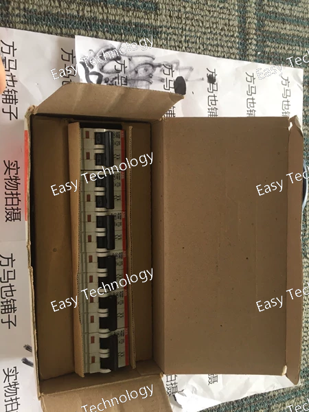
Parameters Category Parameter Specification for S262-C10 General Product Type 2-Pole Miniature Circuit Breaker (MCB) Series System Pro M compact® S200 Poles 2 Poles (2P) Rated Current (In) 10 A per pole Tripping Characteristic "C" Curve (per pole) Electrical Ratings Rated Operational Voltage (Ue) AC 230/400 V (Phase-to-Phase: 400V) Rated Insulation Voltage (Ui) 500 V Rated Frequency 50/60 Hz Breaking Capacity Rated Service Short-Circuit Breaking Capacity (Ics) 6 kA (at 230/400V AC, per IEC/EN 60898-1) Rated Ultimate Short-Circuit Breaking Capacity (Icu) 6 kA Tripping Characteristics (IEC 60898) Overload (Thermal) per pole 1.13 x In (11.3A): No trip within 1 hour. 1.45 x In (14.5A): Must trip within 1 hour. Magnetic Instantaneous Trip per pole 5 x In (50A) to 10 x In (100A). Mechanical & Operational Electrical Life ≥ 10,000 operations (at In) Mechanical Life ≥ 20,000 operations Operation Single, common toggle lever for simultaneous operation of both poles. Terminals Terminal Type Cage Clamp (Spring Loaded) Acceptable Conductor Size Solid/Fine-stranded: 1 - 25 mm² With ferrule: 1 - 16 mm² Mounting Mounting Standard 35 mm symmetrical DIN rail (EN 60715) Width 2 Modules (36 mm) Environmental Operating Temperature -25°C to +55°C (Calibrated at +30°C) Storage Temperature -40°C to +70°C Standards & Approvals Primary Compliance IEC/EN 60898-1 (Electrical accessories) Additional Compliance IEC/EN 60947-2 (Circuit-breakers) Certifications CE, CCC, etc. (Market dependent)
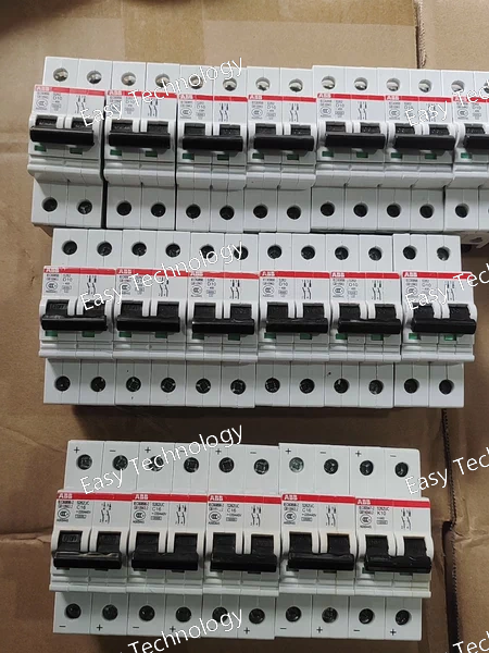
Parameters Category Parameter Specification for S262-C16 General Product Type 2-Pole Miniature Circuit Breaker (MCB) Series System Pro M compact® S200 Poles 2 Poles (2P) Rated Current (In) 16 A per pole Tripping Characteristic "C" Curve (per pole) Electrical Ratings Rated Operational Voltage (Ue) AC 230/400 V (Between poles: 400V) Rated Insulation Voltage (Ui) 500 V Rated Frequency 50/60 Hz Breaking Capacity Rated Service Short-Circuit Breaking Capacity (Ics) 6 kA (at 230/400V AC, per IEC/EN 60898-1) Rated Ultimate Short-Circuit Breaking Capacity (Icu) 6 kA Tripping Characteristics (IEC 60898) Overload (Thermal) per pole 1.13 x In (18.1A): No trip within 1 hour. 1.45 x In (23.2A): Must trip within 1 hour. Magnetic Instantaneous Trip per pole 5 x In (80A) to 10 x In (160A). Mechanical & Operational Electrical Life ≥ 10,000 operations (at In) Mechanical Life ≥ 20,000 operations Operation Single, common toggle lever for simultaneous operation of both poles. Terminals Terminal Type Cage Clamp (Spring Loaded) Acceptable Conductor Size Solid/Fine-stranded: 1 - 25 mm² With ferrule: 1 - 16 mm² Mounting Mounting Standard 35 mm symmetrical DIN rail (EN 60715) Width 2 Modules (36 mm) Environmental Operating Temperature -25°C to +55°C (Calibrated at +30°C) Storage Temperature -40°C to +70°C Standards & Approvals Primary Compliance IEC/EN 60898-1 Certifications CE, CCC, KEMA, etc.
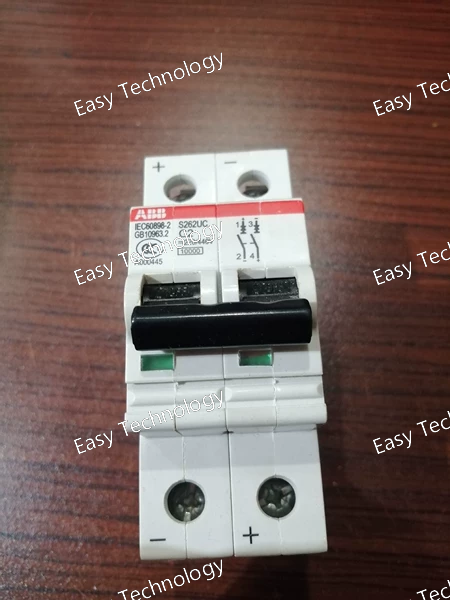
Parameters Category Parameter Specification for S262UC-C2 General Product Type 2-Pole Residual Current Circuit Breaker with Overcurrent Protection (RCBO) Series System Pro M compact® S200 UL Series Poles & Protection 1 Pole + Neutral (1P+N), with both poles switched and protected. Rated Current (In) Not specified in code; common range 6A-32A. Must be verified from label. Overcurrent Curve "C" Curve RCD Type Type AC Residual Current (IΔn) 30 mA Electrical Ratings Rated Voltage (Ue) AC 120/240 V (UL/NEMA market) or 230/400V (IEC market). Rated Frequency 50/60 Hz Breaking Capacity Rated Short-Circuit Capacity (Icn) 2 kA (Indicated by suffix -C2) Tripping Characteristics Overload (Thermal) Per "C" curve: 1.13xIn (no trip <1h), 1.45xIn (trip <1h). Short-Circuit (Magnetic) Per "C" curve: 5xIn to 10xIn. RCD Tripping IΔn = 30mA. Must trip between 0.5xIΔn (15mA) and IΔn (30mA). RCD Non-Tripping ≤ 0.5xIΔn (15mA) must not cause tripping. Operational Electrical Life ≥ 4,000 operations (mechanical) Test Function Integrated "T" test button. Terminals Terminal Type Screw clamp or cage clamp (depending on region/variant). Torque As per marking (e.g., 2.0 Nm). Mounting Mounting Standard 35 mm top-hat DIN rail Width 2 Modules (36 mm) Environmental Operating Temperature -25°C to +60°C Standards & Approvals Primary Compliance IEC/EN 61009-1, IEC/EN 60947-2 Regional Approvals UL 489 (US/Canada), CE (EU)
 TEL: Grace +86 13600179521
  Mail: info@hongkongeasy.com jilineasyyi@outlook.com
 Q Q:615739355
 ADDRESS:Unit 12, 20th Floor, Good View Commercial Centre, 2-16 Garden Street, Mong Kok, Hong Kong
 whats app


