
Industrial Controller
All product are in stock,guaranteed delivery within 3-7 days.


PRODUCT
PICTURE
BRAND
DESCRIBE
STOCK
DOWNLOAD
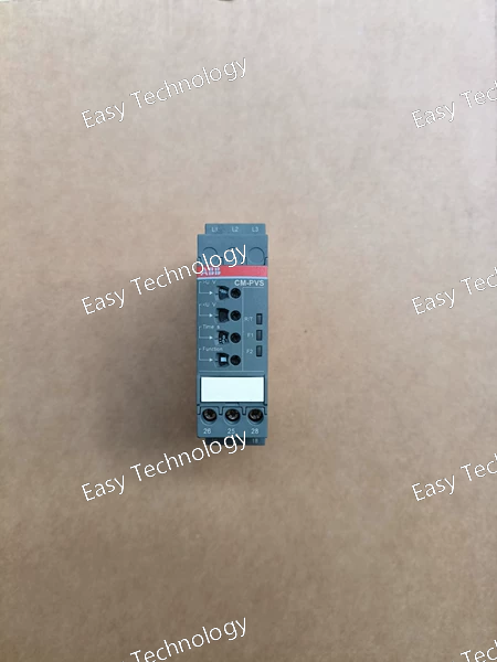
Technical Specifications Specification Value / Description Product Type / Model CM‑PVS.31S three‑phase monitoring relay Part Number 1SVR730794R1300 Monitored / Supply Voltage Range (L–L) 160 … 300 V AC (3‑phase) Supply / Control Voltage (Us) 160 … 300 V AC, 50/60 Hz (same as monitored supply) Functions - Phase failure (phase loss) detection - Phase sequence (phase rotation) monitoring - Over‑ and under‑voltage monitoring - Adjustable thresholds Output Contacts 2 × change‑over (2 c/o / DPDT / 2‑CO) contacts (SPDT pairs) Output / Contact Rating 250 V AC / 4 A (general AC‑12 load) 230 V AC / 3 A (inductive/motor‑control AC‑15 load) 24 V DC / 4 A (DC‑12), 24 V DC / 2 A (DC‑13) Time Functions 200 ms start‑up delay (after power‑up) Trip delay: either instantaneous (0 s) or adjustable 0.1 … 30 s Selectable ON‑delay or OFF‑delay mode Measuring Frequency 50 / 60 Hz Terminal Type / Wiring Screw‑type terminals (double‑chamber cage terminals) Wiring capacity: flexible 1× 0.5–2.5 mm², rigid 1× 0.5–4 mm² (or equivalent) Mounting DIN‑rail (TH35) or suitable panel/rail mounting Dimensions (W × H × D) 22.5 mm × 85.6 mm × 103.7 mm Weight (net) ~ 0.141 kg Operating Ambient Temperature –25 °C … +60 °C Storage Temperature Range –40 °C … +85 °C Insulation & Impulse Withstand Voltage Input circuit / output circuit: 600 V AC; Output circuits: 300 V AC; Impulse withstand (Uimp) — input: 6 kV, output: 4 kV Protection / Housing Housing: IP50; Terminals: IP20 Standards / Approvals Compliant with IEC/EN 60255‑27 (voltage/phase monitoring relays), CAN/CSA C22.2 No. 14, UL/CSA B300 contact rating; RoHS compliant Trip Delay & Configuration Options Adjustable thresholds for over-/under-voltage; adjustable trip delay 0.1–30 s; ON or OFF delay selectable; optionally a sealable transparent cover to prevent unauthorized adjustments
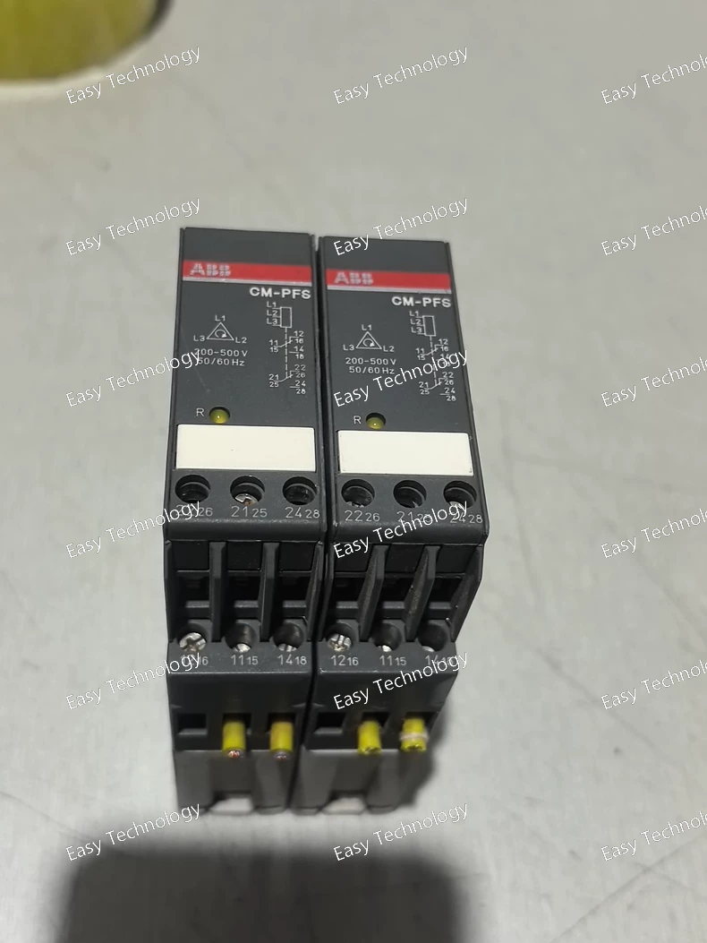
Technical Specifications Parameter / Item Value / Description Product Type / Function Three‑phase monitoring relay (phase sequence + phase‑failure + over/under‑voltage detection) Model / Part Number 1SVR730794R3300 (CM‑PVS.41S) Monitored Voltage (L–L) 300 … 500 V AC, 50/60 Hz Supply / Control Voltage Same as monitored three-phase supply (300–500 V AC) Measured Phase Types 3-phase (L1‑L2‑L3) Output Contacts 2 × change-over (2 c/o, DPDT / SPDT pairs) Contact Rating 250 V AC / 4 A (AC‑12 general load) 3 A @ 230 V AC (AC‑15 inductive / motor‑control load) Also compliant with UL/CSA B300 contact rating, output circuit max 300 V AC Functions Monitored Phase failure (phase loss), phase sequence (phase order), overvoltage / undervoltage, adjustable phase‑unbalance threshold Time Settings / Delay Options 200 ms start‑up delay after power application; selectable trip delay: immediate (0 s) or adjustable 0.1 – 30 s; ON or OFF delay selectable Connection Terminals Screw terminals (double‑chamber cage terminal / spring clamp) suitable for flexible or rigid conductors Mounting DIN‑rail (e.g. TH‑35) mount Operating Ambient Temperature –25 °C … +60 °C Storage Temperature –40 °C … +85 °C Dimensions (W × H × D) 22.5 mm × 85.6 mm × 103.7 mm Net Weight ~ 0.139 kg Standards / Approvals IEC/EN for phase monitoring relays; UL/CSA output contact rating B300; RoHS compliant Additional Features Adjustable undervoltage/overvoltage thresholds, adjustable trip delay, LED (or status indication) (depending on variant), transparent/sealable cover option to prevent unauthorized adjustment
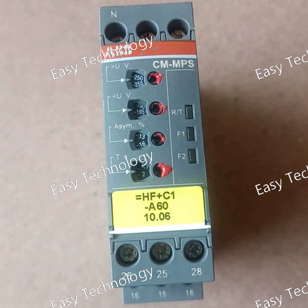
Technical Specifications Parameter Value / Description Product Type / Function Three-phase monitoring relay (phase-sequence & phase-loss) Part Number 1SVR430824R9300 Monitored Voltage Range (L–L) 200 … 500 V AC, 50/60 Hz Supply / Control Voltage Powered by measured supply (200–500 V AC, 50/60 Hz) Output Contacts 2 change-over contacts (DPDT) Contact Rating 4 A @ 230 V AC (AC‑12), 3 A @ 230 V AC (AC‑15) Terminal Type Screw terminals Mounting DIN-rail (TH‑35) Response / Startup Delay 500 ms Operating Frequency 50 / 60 Hz Ambient / Operating Temperature –25 °C … +60 °C Storage Temperature –40 °C … +85 °C Dimensions Width: 22.5 mm, Height: 85.6 mm, Depth: 103.7 mm Weight Approx. 0.127 kg Standards / Certifications IEC / EN compliant for phase monitoring; UL/CSA contact rating B300 Functions Phase sequence checking, phase loss detection, under-/over-voltage detection, DPDT relay output
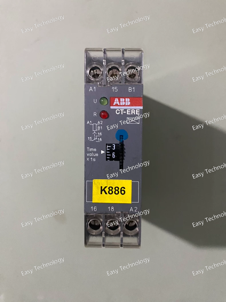
Technical Specifications Parameter / Item Value / Description Product Type / Function Electronic timer relay — ON‑delay (delay‑on‑make) Part Number 1SVR550107R4100 (model name: CT‑ERE) Time Range / Delay Setting 0.3 … 30 seconds Control / Supply Voltage (Us) 24 V AC/DC or 220–240 V AC Output Contacts 1 change‑over contact (1 C/O, SPDT) Output Rating 250 V AC / 4 A (max) Utilization / Load Ratings • AC‑12 (resistive/general load): 4 A @ 230 V AC • AC‑15 (inductive / motor‑control load): 3 A @ 230 V AC • DC‑12: 4 A @ 24 V DC • DC‑13: 2 A @ 24 V DC Mounting / Terminals DIN‑rail (e.g. TH35) mounting, screw‑terminal connections Dimensions Width: 22.5 mm Height: 78 mm Depth: 78.5 mm Net weight: ~ 0.067 kg Operating Temperature Range –20 °C … +60 °C (typical for control‑relay class) Housing / Protection / Standards Terminals: IP20; Compliant with standards IEC/EN 61812‑1, CAN/CSA C22.2 No.14, UL 508; RoHS compliant Mounting Positions Any (1…6) according to mounting guidelines
Technical Specifications Specification Value / Description Contactor Type Miniature 3‑pole contactor relay Main Contacts 3 × Normally‑Open (NO) Auxiliary Contacts None (standard variant) Coil / Control Circuit DC or AC coil depending on variant; low-power design suitable for PLC or DC control logic Rated Main-Circuit Voltage (Ue) Up to 400–690 V AC (depending on application) Rated Insulation Voltage (Ui) 400–690 V AC Impulse Withstand Voltage (Uimp) 4–6 kV Rated Operational Current (AC‑1, Ie) 6–10 A typical, depending on voltage and variant Motor / Inductive Load (AC‑3) Small motors up to 1.5–2 kW (depending on voltage) Short-Time Withstand Current (Icw) 30–50 A for 10 s (cold start, ambient 40 °C) Coil Operating Limits 0.85 … 1.10 × rated coil voltage Mechanical / Electrical Life ~10,000,000 switching cycles Terminal / Connection Screw terminals for main and auxiliary circuits; compact wiring footprint Mounting DIN-rail (TH35) or panel mounting Operating / Environmental Conditions Ambient temperature: –25 … +55 °C; Storage: –40 … +80 °C; Max installation altitude: ~2000 m Standards / Certifications IEC/EN 60947‑1, 60947‑4‑1; UL/CSA approved where applicable
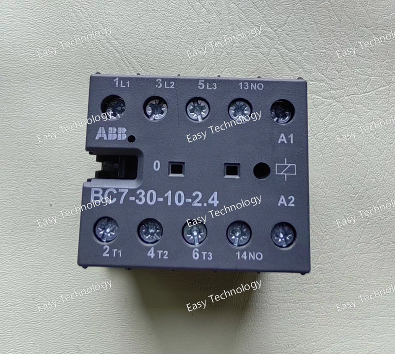
Technical Specifications Specification Value / Description Contactor Type 3‑pole mini‑contactor (non-reversing) Main Contacts 3 × Normally‑Open (NO) Auxiliary Contacts 1 × Normally‑Open (NO) Coil / Control Circuit DC coil, rated 17–32 V DC, coil power ≈ 2.4 W Rated Main-Circuit Voltage (Ue) Up to 690 V AC Rated Insulation Voltage (Ui) 690 V AC Impulse Withstand Voltage (Uimp) 6 kV Rated Operational Current (AC‑1, Ie, resistive/general load) 20 A @ 220–240 V AC (40 °C) 16 A @ 220–240 V AC (55 °C) 20 A @ 380–440 V AC (40 °C) 16 A @ 380–440 V AC (55 °C) 6 A @ 690 V AC Rated Motor (AC‑3) Load / Power 3 kW @ 230 V AC three-phase 5.5 kW @ 400 V AC three-phase 5.5 kW @ 500 V AC three-phase 3 kW @ 690 V AC three-phase Short-time Withstand Current (Icw) 96 A for 10 s (cold start, free air, 40 °C ambient) Coil Operating Limits 0.85 … 1.10 × Uc Mechanical / Electrical Endurance Up to 10,000,000 switching cycles Connection / Terminals Flat‑pin or solder‑pin, suitable for small conductor cross-section Mounting DIN‑rail or panel mounting; compact footprint Ambient / Environmental Conditions Operating: –25 °C … +55 °C; Storage: –40 °C … +80 °C; Max installation altitude: ~2000 m
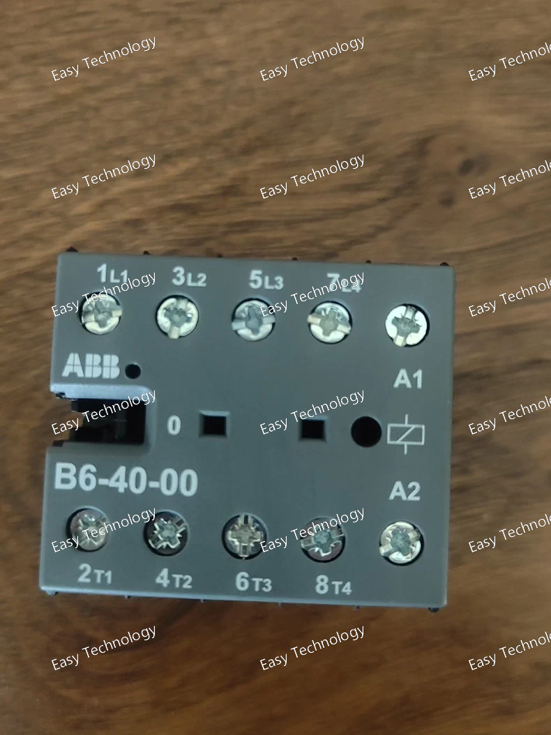
Technical Specifications Parameter Value / Description Contactor Type Miniature 4‑pole contactor (mini contactor) Main Contacts 4 × Normally‑Open (NO) Auxiliary Contacts None (standard model) Rated Main‑Circuit Voltage (Ue) Up to 690 V AC (main circuit) Rated Insulation Voltage (Ui) 690 V AC (accord. to IEC); 600 V AC per UL/CSA when applicable Impulse Withstand Voltage (Uimp) 6 kV (main circuit) Rated Operational Current — AC‑1 (Ie, resistive / general load) 20 A @ 220–240 V AC (ambient 40 °C) 16 A @ same voltage (ambient 55 °C) 20 A @ 380–440 V AC (40 °C) 16 A @ 380–440 V AC (55 °C) 6 A @ 690 V AC (both 40 °C & 55 °C) Rated Motor / Inductive Load — AC‑3 (Ie / Power capability) Up to: ~ 2.2 kW @ 230 V AC (three‑phase) ~ 4.0 kW @ 400 V AC (three‑phase) ~ 4.0 kW @ 500 V AC ~ 3.0 kW @ 690 V AC (three‑phase) Short‑time Withstand Current (Icw) 64 A for 10 seconds (cold start, free air, 40 °C ambient) Conventional Free‑air Thermal Current (Ith) 20 A Control Coil / Coil Type / Rated Coil Voltage (Uc) AC‑operated coil; typical coil‑voltage variants depend on version (e.g. 220–240 V AC, 24 V AC, etc.), designed per IEC 60947‑4‑1 Coil Operating Limits 0.85 … 1.1 × Uc (for ambient ≤ 55 °C) Terminal / Connection Types Screw‑terminal, flat‑pin, or solder‑pin options depending on variant; suitable for small to moderate conductor cross‑section Mounting / Installation Wall/panel mounting or DIN‑rail mounting (e.g. TH35) — compact design for limited‑space cabinet or panel installations Mechanical / Electrical Durability Mechanical life up to 10,000,000 switching cycles; suitable for frequent switching in control or automation environments Typical Use Cases Lighting and heating circuits, small motor loads (pumps, fans), HVAC systems, small industrial machines, general-purpose AC loads in control panels or buildings, retrofit or new installations when compact size is needed
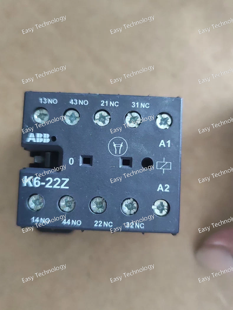
Technical Specifications Parameter / Item Value / Description Contactor Type 4‑pole mini contactor relay (mini‑contactor) Coil / Control Circuit DC‑coil, 220–240 V DC (standard “‑05” variant) Coil Operating Tolerance 0.85 … 1.10 × Uc (at ambient ≤ 55 °C) Coil Power Consumption ~ 3.5 W (holding and pull-in) Main / Auxiliary Contacts Configuration 4 poles (main contacts), ... plus auxiliary contact set (as per variant: 3 NO + 1 NC auxiliary contacts) Rated Insulation Voltage (Ui) 690 V AC (with 600 V rating under UL/CSA) Rated Impulse Withstand Voltage (Uimp) 6 kV (auxiliary / control circuit) Rated Operational Voltages (Main / Auxiliary) Up to 690 V AC (main circuit); auxiliary / control circuits per coil/version Switching / Load Capability (AC‑15 / Control Signals) Up to ~3 A @ 400 V AC (AC‑15 utilization) Switching / Load Capability (DC‑13 / DC Loads) at 24 V DC: up to ~2.5 A; at 110 V DC: ~0.7 A; at 220–240 V DC: ~0.4 A Conventional Thermal Current (Ith) 6 A (auxiliary circuit rating) Switching Frequency & Life Electrical / mechanical life ~10,000,000 cycles; switching frequency up to 600 cycles/hour (AC‑15 or DC‑13) Minimum Switching Capacity 17 V / 5 mA (i.e. supports low‑level signals) Connection / Terminals Screw terminals for main and auxiliary circuits; accepted conductor sizes: flexible with ferrule 1 … 2.5 mm², rigid 1 … 4 mm² Mounting Options DIN‑rail mounting (e.g. TH35) or panel mounting; minimum horizontal clearance 0 mm (i.e. can be mounted side‑by‑side with same devices) Dimensions & Weight Width 52.5 mm; Height 57.5 mm; Depth 46.5 mm; Net weight ~ 0.175 kg Operating Environment Ambient operation: –25 … +55 °C; Storage: –40 … +80 °C; Max installation altitude: ~2000 m Protection & Standards Auxiliary/control terminals: IP20; Compliant with IEC/EN 60947‑1, 60947‑4‑1, 60947‑5‑1; UL/CSA contact‑rating A600, general‑use 600 V AC 5 A
Technical Specifications Specification Value / Description Contactor Type 4‑pole miniature contactor Main Contacts 4 × Normally‑Open (NO) Auxiliary Contacts None Control / Coil Circuit DC-operated coil (e.g., 24 V DC) Rated Main-Circuit Voltage (Ue) Up to 690 V AC Rated Insulation Voltage (Ui) 690 V AC Impulse Withstand Voltage (Uimp) 6 kV Rated Operational Current (AC‑1, Ie) 20 A @ 220–240 V AC (40 °C) / 16 A (55 °C) 20 A @ 380–440 V AC (40 °C) / 16 A (55 °C) 6 A @ 690 V AC Motor / Inductive Load (AC‑3) 3 kW @ 230 V AC three‑phase 5.5 kW @ 400 V AC three‑phase 3 kW @ 690 V AC three‑phase Short-Time Withstand Current (Icw) 96 A for 10 s (cold start, 40 °C ambient) Electrical / Mechanical Life Rated for ~10 million switching cycles Terminal / Connection Screw-terminal or cable-clamp for main circuit Mounting / Installation DIN‑rail or panel mounting; compact size for space-constrained cabinets Operating / Environmental Conditions Operating ambient: –20 … +55 °C; Storage: –40 … +80 °C; Max installation altitude: ~2000 m
Technical Specifications Specification Value / Description Contactor Type Miniature 3‑pole contactor Main Contacts 3 × Normally‑Open (NO) Auxiliary Contacts 1 × Normally‑Closed (NC) Rated Main-Circuit Voltage (Ue) Up to 690 V AC Insulation Voltage (Ui) 690 V AC Impulse Withstand Voltage (Uimp) 6 kV Rated Operational Current (AC‑1, Ie) 20 A @ 220–240 V AC (40 °C) / 16 A (55 °C) 20 A @ 380–440 V AC (40 °C) / 16 A (55 °C) 6 A @ 690 V AC Rated Operational Power (AC‑3, Motor Load) ~3.0 kW @ 230 V AC three‑phase ~5.5 kW @ 400 V AC three‑phase ~3.0 kW @ 690 V AC three‑phase Short-Time Withstand Current (Icw) 96 A for 10 s (cold start, free air, 40 °C ambient) Rated Coil / Control Voltage (Uc) Depends on variant — e.g., 12 V DC or AC/DC options Electrical / Mechanical Life Mechanical life up to ~10 million operations; switching frequency moderate (mini‑contactor class) Terminal / Connection Screw terminals or solder-pin for main circuit; terminals for coil as per variant Environmental / Operating Conditions Operating ambient: –25 … +55 °C; Storage: –40 … +80 °C; suitable for installation up to ~2000 m altitude Typical Applications Small three‑phase motors (pumps, fans, small compressors) Light/medium industrial loads, control circuits, lighting, HVAC systems Compact control panels or automation cabinets General AC switching where moderate currents are required and heavy-duty contactors are not needed
Technical Specifications Specification Value / Description Contactor Type Miniature 3‑pole contactor Main Contacts 3 × Normally‑Open (NO) Auxiliary Contacts Typically none Rated Main-Circuit Voltage (Ue) Up to 690 V AC Insulation Voltage (Ui) 690 V AC Impulse Withstand Voltage (Uimp) 6 kV Rated Operational Current (AC‑1, Ie) 20 A @ 220–240 V AC (40 °C) / 16 A (55 °C) 20 A @ 380–440 V AC (40 °C) / 16 A (55 °C) 6 A @ 690 V AC Rated Operational Power (AC‑3, Motor Load) ~3.0 kW @ 230 V AC three‑phase ~5.5 kW @ 400 V AC three‑phase ~3.0 kW @ 690 V AC three‑phase Short-Time Withstand Current (Icw) 96 A for 10 s (cold start, free air, 40 °C ambient) Rated Coil / Control Voltage (Uc) Depends on variant — e.g., 12 V DC or other AC/DC versions Electrical / Mechanical Life Mechanical life up to ~10 million operations; switching frequency moderate (mini‑contactor class) Terminal / Connection Screw terminals or solder-pin for main circuit; terminals for coil as per variant Environmental / Operating Conditions Operating ambient: –25 … +55 °C; Storage: –40 … +80 °C; suitable for installation up to ~2000 m altitude Typical Applications Small three‑phase motors (pumps, fans, small compressors) Light/medium industrial loads, control circuits, lighting, HVAC Compact control panels or automation cabinets where space is limited General AC switching where a small, reliable, and economical contactor is needed
Technical Specifications Parameter Value / Description Contactor Type Miniature 3‑pole contactor (non-reversing) Main Contacts 3 × Normally‑Open (NO) Auxiliary Contacts 1 × Normally‑Closed (NC) Rated Main-Circuit Voltage (Ue) Up to 690 V AC Rated Insulation Voltage (Ui) 690 V AC Impulse Withstand Voltage (Uimp) 6 kV Rated Operational Current (AC‑1, Ie) 20 A @ 220–240 V AC (40 °C) 16 A @ 220–240 V AC (55 °C) 20 A @ 380–440 V AC (40 °C) 16 A @ 380–440 V AC (55 °C) 6 A @ 690 V AC Rated Operational Power (AC‑3, Motor Load) ~2.2 kW @ 230 V AC three‑phase ~4.0 kW @ 400 V AC three‑phase ~3.0 kW @ 690 V AC three‑phase Short-Time Withstand Current (Icw) 64 A for 10 s (cold start, free air, 40 °C) Coil / Control Voltage (Uc) Typical coil variants include 24 V DC; may vary by version Auxiliary Contact Ratings AC‑15: up to 4 A @ 120–240 V AC; DC‑13: 2.5 A @ 24 V DC Mounting & Connection DIN‑rail or wall/panel mounting; screw terminals for main and auxiliary contacts Dimensions & Weight ~52.5 mm (W) × 57.5 mm (H) × 46.5 mm (D); ~0.175 kg Mechanical / Electrical Life Up to 10,000,000 operations; switching frequency up to 300–600 cycles/hour depending on load type Ambient / Environmental Operating: –25 °C … +55 °C; Storage: –40 °C … +80 °C
 TEL: Grace +86 13600179521
  Mail: info@hongkongeasy.com jilineasyyi@outlook.com
 Q Q:615739355
 ADDRESS:Unit 12, 20th Floor, Good View Commercial Centre, 2-16 Garden Street, Mong Kok, Hong Kong
 whats app


