
Industrial Controller
All product are in stock,guaranteed delivery within 3-7 days.


PRODUCT
PICTURE
BRAND
DESCRIBE
STOCK
DOWNLOAD
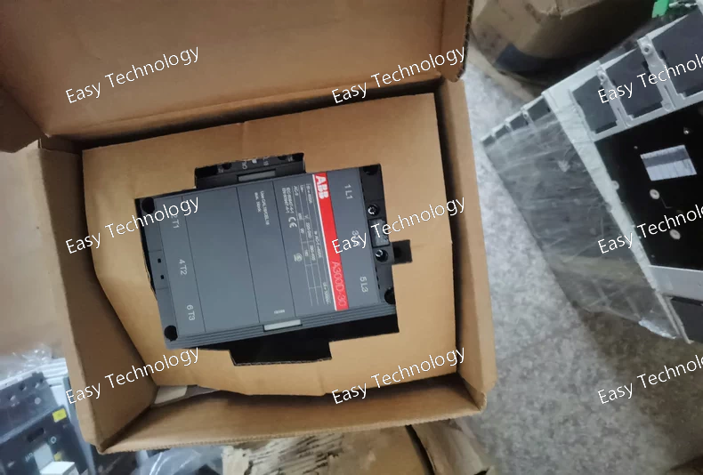
Technical Parameters Parameter / Feature Specification / Detail Model / Type A300D‑30‑11 (3‑pole AC contactor) Main Contacts (Power) 3 poles — 3 × Normally‑Open (3 NO) Auxiliary Contacts 1 × Normally‑Open (NO) + 1 × Normally‑Closed (NC) auxiliary contact block Rated Main‑Circuit Voltage (Ue) Up to 690 V AC (IEC rating) Rated Operational Current (AC‑1, Ie) Up to ~ 500 A at 690 V (at 40 °C free air rating) Current at Higher Temperatures / Derating e.g. 400 A @ 55 °C, 325 A @ 70 °C (depending on configuration) Motor Duty Rating (AC‑3, Ie) ~ 300 A at 415 V AC (motor‑load switching) Rated Operational Power (AC‑3, Pe) e.g. 160 kW @ 400–440 V, up to 250 kW at 690 V (depending on supply & load) Making / Breaking Capacity (AC‑3) Making capacity 10× Ie; Breaking capacity 8× Ie (per IEC 60947‑4‑1) Short‑Circuit / Withstand Current (Icw) / Capacity High short‑circuit and making capacity — suitable for strong industrial loads / motor starts / inrush currents Coil / Control Circuit Available in various coil voltages depending on variant (AC coil; many common coil‑voltage versions exist) Insulation & Impulse Withstand Voltage (Ui / Uimp) Insulation rating per IEC: Ui ≈ 1000 V; impulse‑withstand approx 8 kV Terminals / Connections Screw / bar‑type main‑circuit terminals (for heavy cables / busbars); standard auxiliary‑contact terminals for control wiring Mechanical Durability / Lifetime Designed for industrial heavy‑duty use, high cycle life and robust mechanical construction Typical Applications Three‑phase motor control (start/stop), heavy machinery, industrial load switching, power distribution panels, load isolation/bypass, pump/compressor control, general 3‑phase AC circuits
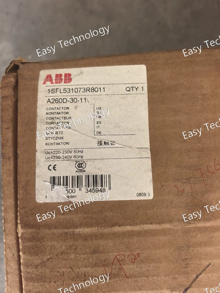
Technical Parameters Parameter / Feature Specification / Detail Model / Series A260D‑30‑11 (3‑pole AC contactor) Poles / Main Contacts 3 main contacts (3P), normally‑open (3 NO) Auxiliary Contacts 1 NO + 1 NC Rated Operational Voltage (Main Circuit) Up to 690 V AC Conventional Free‑air Thermal Current (Ith) 400 A at 40 °C Rated Operational Current — AC‑1 400 A @ 690 V (derated 350 A @ 55 °C, 290 A @ 70 °C) Rated Operational Current — AC‑3 260 A @ 415 V; 240 A @ 440–500 V; 220 A @ 690 V Max Motor Power (AC‑3) ~200 kW (depending on voltage & load conditions) Coil / Control Voltage Multiple variants (AC or DC, depending on ordering code) Terminals Main: bar-type for high-current cables/busbars; Auxiliary: screw-type Mechanical / Electrical Endurance Designed for heavy-duty industrial use; high cycle life Insulation / Impulse Withstand Voltage Ui = 1000 V; Uimp ≈ 8 kV Standards IEC 60947‑4‑1 compliant Operating Conditions Ambient temperature: –25 °C … +50 °C (with overload relay); –40 °C … +70 °C (without overload relay) Typical Applications Three-phase motor control, heavy load switching, industrial machinery, power distribution panels

Technical Parameters Parameter / Feature Specification / Detail Model / Type A260‑30‑11 (3‑pole AC contactor) Poles / Main Contacts 3 main contacts — 3 × Normally‑Open (NO) Auxiliary Contacts 1 × NO + 1 × NC (auxiliary contact block) Rated Operational Voltage (Main Circuit) Up to 690 V AC Rated Operational Current (AC‑1, Ie) 400 A (at 690 V, 40 °C free‑air); derates to 350 A at 55 °C, 290 A at 70 °C Rated Operational Current (AC‑3, Ie, motor switching) 260 A @ 415 V AC; 240 A @ 440 – 500 V AC; 220 A @ 690 V AC; (also 260 A @ 220‑240 V for lower‑voltage motors) Rated Operational Power (AC‑3, 400 V) 140 kW (three‑phase motor load) Utilization Category AC‑1 (general loads) and AC‑3 (motor loads) supported Insulation / Impulse Withstand Voltage Ui = 1000 V (IEC), Uimp = 8 kV Mechanical / Thermal Current Rating (Ith) 400 A at 40 °C free‑air Coil / Control Voltage Many variants — common AC coil versions: 220–230 V AC (50 Hz) or 230–240 V AC (60 Hz); other coils available depending on ordering code Frequency (Main Circuit) 50 / 60 Hz Connection / Terminals Bar‑type main terminals (for heavy cables or busbars); screw‑type auxiliary terminals; suitable for high‑capacity wiring Operating / Ambient Conditions Standard industrial ambient (typical –25 °C … +50 °C when fitted with thermal overload relay; wider storage/ non‑loaded range) Enclosure / Mounting DIN‑rail or panel / busbar installation (depending on variant); NEMA/IEC rated enclosure class per installation Typical Applications Three‑phase motor start/stop, industrial motor control, heavy‑load switching, power distribution panels, motor bypass/ isolation, general high‑power AC three‑phase circuits
Technical Parameters Parameter / Feature Specification / Detail Model / Type A320‑30‑11 (3‑pole AC contactor) Poles / Main Contacts 3 main contacts (3‑pole), normally‑open (NO) Auxiliary Contacts Depending on version: some variants have 0 auxiliary contacts, some have 1 NC auxiliary contact Rated Control (Coil) Voltage Example variants: 48 V AC 50 Hz; 110 V AC 50 Hz — other coil voltages possible depending on version Maximum Main‑Circuit Voltage Up to ~ 600 V AC (for typical applications) Main‑Circuit Connection Type Bar‑type terminals / busbar‑type main‑circuit connection Contactor Dimensions (approx.) Width ~ 140 mm; Depth ~ 180.5 mm; Height ~ 227 mm Application Types Motor starting, isolation, bypass, distribution, general three‑phase load switching Main Contact Configuration 3 NO main contacts; no NC main contacts Auxiliary Contact Configuration (some variants) 0 or 1 NC auxiliary contact (depending coil version / variant) Intended Use AC switching in three‑phase circuits, load control, motor switching, power distribution
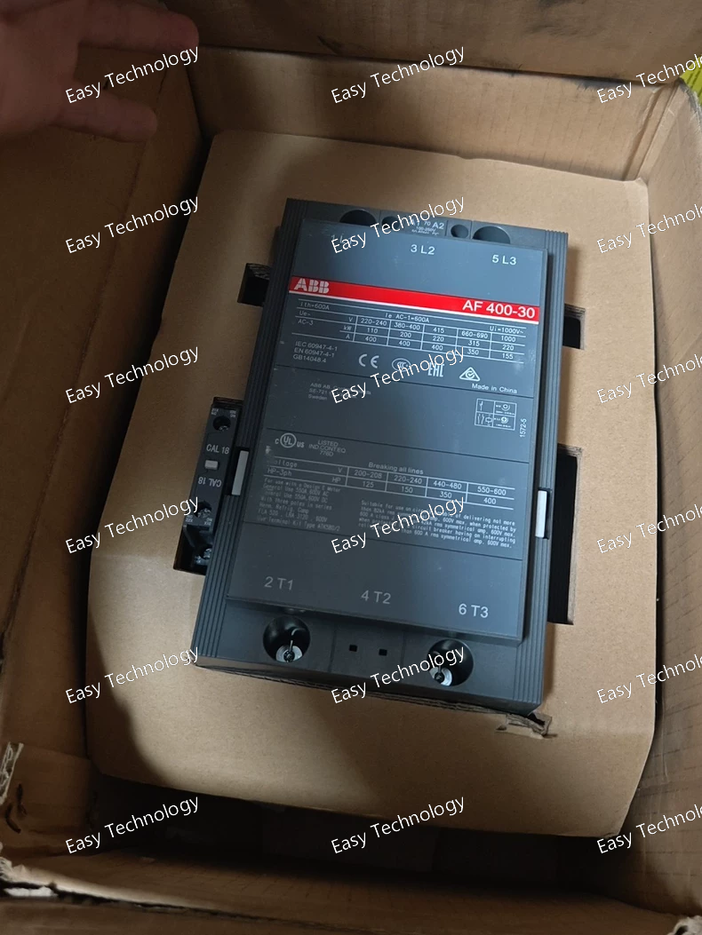
Technical Parameters Parameter / Feature Specification / Detail Model / Type AF400‑30‑11 3‑pole Contactor Main Contact Poles 3 (3‑pole), 3 × Normally‑Open (NO) main contacts Auxiliary Contacts 1 × NO + 1 × NC auxiliary contact block Rated Operational Voltage (Main Circuit) Up to 1000 V AC (IEC rating) Rated Operational Current (AC‑1, general use) Up to 600 A (at 690–1000 V, depending on ambient temp) Motor Load Rating (AC‑3) Up to ~400 A @ 400‑415 V; ~350 A @ 690 V (for motor‑load duty) Maximum Power Handling (AC‑3) Up to ~250 kW–315 kW (depending on voltage & load) Coil / Control Voltage Range Depending on variant: e.g. 100–250 V AC / DC (other coil voltages available) Utilisation Category Suitable for general load switching (AC‑1) and motor switching (AC‑3) duties Contact Making/Breaking Capacity Making capacity up to 10× Ie; breaking capacity up to 8× Ie (per IEC‑60947‑4‑1 for contactors) Terminals / Connections Main circuit: bar‑type terminals (for high-current cables / busbars); Auxiliary: screw‑type terminals Mechanical Durability / Switching Frequency Designed for heavy industrial use, typical mechanical endurance and switching cycles suitable for frequent switching Ambient / Environmental Conditions Operating temperature roughly –40 °C to +70 °C (depending on coil variant and installation); suitable for industrial environments Typical Applications Three‑phase motor start/stop control, heavy load switching, industrial machinery control, power distribution panels, large 3‑phase loads
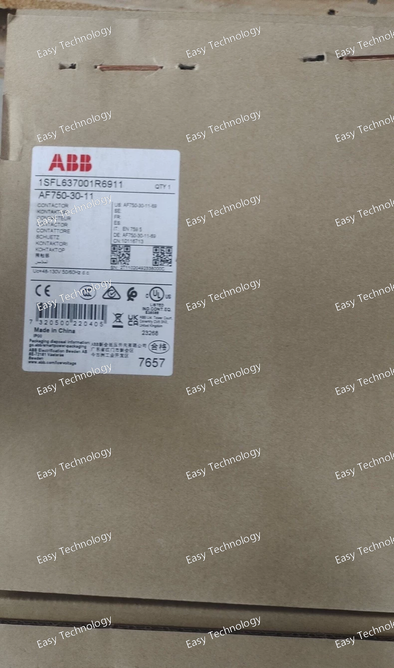
Technical Parameters Parameter / Feature Specification / Detail Model / Type AF750‑30‑11‑69 (AF750 series 3‑pole contactor) Number of Poles (Main Contacts) 3 poles — 3 × Normally‑Open (NO) main contacts Auxiliary Contacts 1 × Normally‑Open (NO) + 1 × Normally‑Closed (NC) auxiliary contact Control / Coil Voltage Range 48–130 V AC or 48–130 V DC (some variants in AF750 series support wider ranges) Main Circuit Rated Operational Voltage Up to 1000 V AC (IEC), 600 V AC (UL/CSA) Rated Current / Load Capacity (AC‑1, General Use) Up to 1050 A (AC‑1, free‑air rating at 400 V) Motor‑Switching (AC‑3) Current / Load Capacity Up to 750 A (motor‑load rating) under appropriate conditions Rated Operational Power (Motor / Load) Up to 400 kW at 400 V (three‑phase) — depending on conditions and supply voltage Contact Configuration 3 NO (power) + auxiliary NO/NC contacts Insulation Voltage (Ui) 1000 V (IEC rating) Impulse Withstand Voltage (Uimp) ~ 8 kV Protection / Enclosure / Terminals Main terminals: bar‑type / lug / bolt connection; auxiliary: screw terminals; Main circuit terminals typically IP00, coil/aux terminals IP20 Ambient / Operating Temperature Typical range –40 °C … +70 °C (depending on coil, ambient, and applied overload relay) Mechanical / Electrical Endurance Designed for heavy industrial use (high cycle life, robust construction) Typical Applications Three‑phase motor start/stop, heavy‑duty motor control, power circuits switching, motor bypass/isolation, industrial machinery, large load switching, switchgear, distribution panels
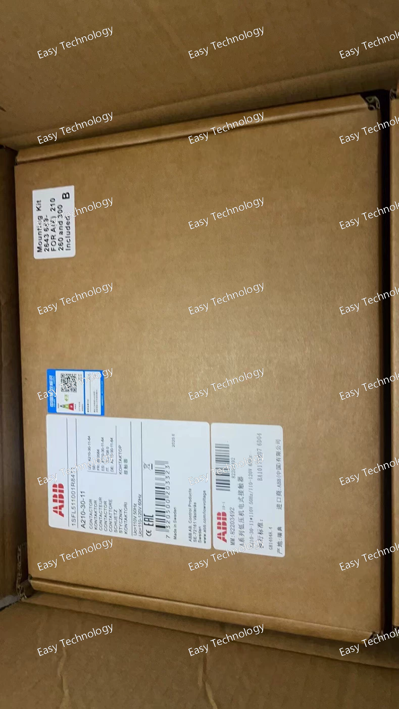
Technical Parameters Parameter / Feature Specification / Detail Model / Type A210‑30‑11 (3‑pole contactor) Main Poles / Contacts 3 poles — 3 × Normally‑Open (NO) main contacts Auxiliary Contacts 1 × NO + 1 × NC auxiliary contact block Rated Operational Voltage (Main Circuit) Up to 690 V AC Rated Operational Current (AC‑1) up to ~ 350 A at 690 V (at 40 °C, free‑air) Rated Operational Current (AC‑3, motor switching) ~ 210 A at 400–690 V (ambient 55 °C) Rated Motor Power (AC‑3) ~ 110 kW at 415 V; higher at higher voltages (depending on load) Coil / Control Voltage Many variants — common coil voltages include 110 V AC (50 Hz) / 115 V AC (60 Hz); other control‑voltage versions available Insulation Voltage / Withstand Insulation rating per IEC; impulse‑withstand voltage ~ 8 kV Terminals / Connection Bar‑type main terminals (suitable for heavy cables/busbars); screw‑type auxiliary terminals Dimensions & Weight (approx.) Width ~140 mm; Depth ~180.5 mm; Height ~227 mm; Weight ~5.4 kg (varies with variant) Operational Environment Ambient operating temperature nominal range; suitable for industrial use, up to certain altitude, subject to derating at higher temperature Typical Applications Motor start/stop control, three‑phase load switching, industrial machinery control, power distribution panels, bypass/isolation circuits
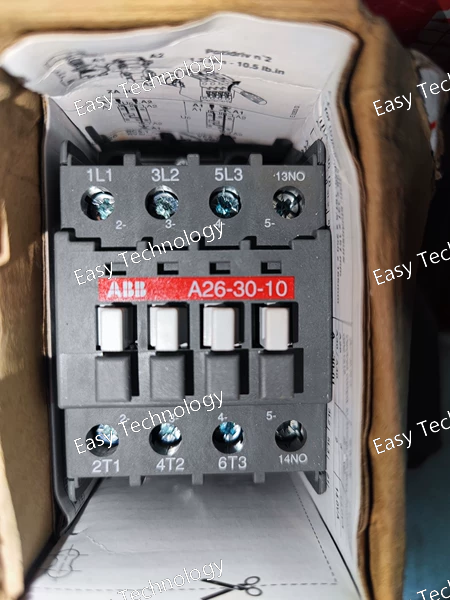
Technical Parameters Parameter / Feature Specification / Detail Model / Type A30‑30‑10 AC Contactor Poles / Main Contacts 3 main contacts (3‑pole) — normally‑open (NO) Auxiliary Contacts 1 auxiliary contact (1 NO built‑in) + optional add‑on blocks if required Rated Operational Voltage (Main Circuit) Up to 690 V AC (some variants support up to ~1000 V depending on configuration) Rated Current (AC‑1, Ie) 55 A @ 690 V AC (ambient 40 °C) Load Current / Thermal Current (Ith) 65 A (free‑air, 40 °C) Rated Operational Current for AC‑3 (Motor Switching) ~ 32–55 A (depending on supply voltage and ambient conditions) Rated Operational Power (AC‑3) For motors/loads: ~ 15 kW (at 380–415 V AC), lower at higher voltages Control (Coil) Voltage Various coil-voltage variants — common one: 230–240 V AC (50/60 Hz) Standard Compliance Conforms to IEC 60947‑1 / IEC 60947‑4‑1 (standard for low‑voltage AC contactors) Mounting / Terminals Block‑type design; screw‑terminals for main and auxiliary contacts; mounting on panel or DIN‑rail (depending variant) Suitability / Typical Applications Three‑phase motor control (start/stop), lighting / power circuits switching, general industrial power control, capacitor switching, load switching, distribution boards
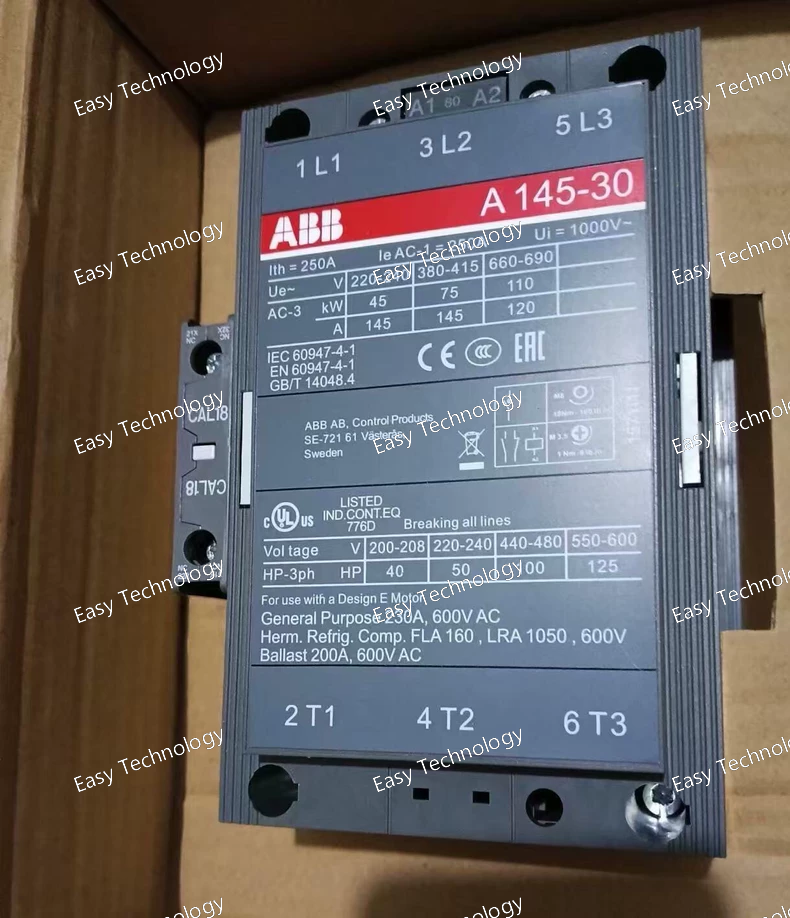
Technical Parameters Parameter / Feature Specification / Detail Model A145‑30‑11 (ABB A‑line) Number of Poles (Main Contacts) 3 (3‑pole) Main Contact Configuration 3 × NO (normally‑open) main contacts Auxiliary Contacts 1 NO + 1 NC (auxiliary / control contacts) Conventional Free‑air Thermal Current (Ith) 250 A (at 40 °C free‑air) Rated Operational Current (AC‑1, Ie) 250 A (at 690 V AC, 40 °C) Rated Operational Current (AC‑3, Ie) ~ 145 A (at 400–415 V AC, 55 °C) Rated Operational Voltage (Main Circuit) Up to 690 V AC (some variants spec up to 1000 V) Rated Operational Power (AC‑3) / Motor Load Capacity - 45 kW at 220–240 V AC - 75 kW at 380–415 V AC - 110 kW at 500–690 V AC (approximate, depending on supply and load) Coil Voltage (Control) AC‑operated, various coil‑voltage variants available (e.g. 220–230 V AC for many versions) Standards IEC 60947‑4‑1 / EN 60947‑4‑1 compliant (standard for motor‑control contactors) Auxiliary / Control Options Compatible with auxiliary contact blocks / accessories (side‑ or top‑mount) for extended functionality Typical Applications Three‑phase motor control (start/stop), contactor switching, load distribution, motor bypass/isolation, HVAC, pumps, compressors, general industrial loads
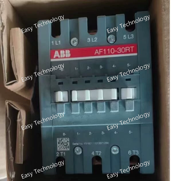
Technical Parameters Parameter / Feature Specification / Detail Series / Model AF110‑30‑11 (3‑pole contactor) Poles (Main Contacts) 3 main poles, normally‑open (3 NO) Auxiliary Contacts 1 NO + 1 NC (or per variant) auxiliary contact block Main Circuit Rated Voltage Up to 690 V AC (some versions up to 1000 V AC, depending on coordination) Control (Coil) Voltage Range Wide-range: e.g. 100–250 V AC or DC (many variants) — suitable for 50/60 Hz supply or DC control circuits Utilization / Application Motor control, general-purpose power switching, 3‑phase load switching, industrial machinery, HVAC, pumps, compressors, etc. Rated Operational Current / Load Capacity Rated for heavy loads (frame AF110) — suitable for high current and high-power circuits (see application rating table per motor / load type) Insulation / Surge & Impulse Ratings Insulation voltage ~1000 V; impulse withstand voltage U_imp ~8 kV (suitable for industrial environment) Operating Temperature & Environment Ambient range (depending on coil and mounting) typically from –40 °C to +70 °C (without overload relay), broader storage range; designed for industrial environments. Standards & Compliance Compliant with IEC 60947‑1 / IEC 60947‑4‑1 (for AC contactors), and typical national/international standards for motor and power contactors. Mounting / Installation Standard DIN‑rail or panel / busbar mounting; screw‑type main and auxiliary terminals; supports solid, stranded, or lug-type cables per connection guidelines. Typical Uses Three-phase motor start/stop control; power-circuit switching; industrial machine control; HVAC, pumps/compressors; general power distribution switching where robust contactor is needed.
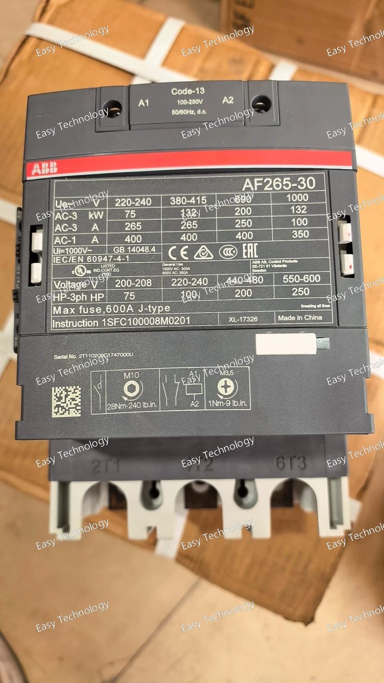
Technical Parameters Parameter / Feature Specification / Detail Model / Type AF265‑30‑11‑13 (ABB AF series contactor) Poles / Contacts 3 main contacts (3‑pole, 3 NO) + 1 auxiliary contact block (1 NO + 1 NC) Control Coil Voltage 100–250 V AC or 100–250 V DC (50/60 Hz) — wide‑range coil Main Circuit Rated Insulation Voltage (Ui) 1000 V (IEC) / 600 V (UL/CSA) Rated Operational Voltage (Main Circuit) Up to 1000 V AC Rated Operational Current (AC‑1) Up to 350 A at 1000 V (40 °C) Rated Operational Current (AC‑3) / Motor Switching 265 A at 400‑415 V AC; 250 A at 500‑690 V AC Rated Motor Power (AC‑3) Up to ~132 kW at 400 V AC; higher depending on voltage (e.g. ~200 kW at 690 V) Making / Breaking Capacity Making capacity: 10 × Ie (AC‑3); Breaking capacity: 8 × Ie (AC‑3) Rated Impulse Withstand Voltage (Uimp) 8 kV Coil Features Electronic coil interface with reduced power consumption; built‑in surge suppression; tolerant of voltage dips/sags Auxiliary/Accessories Built‑in 1NO + 1NC auxiliary contact; optional add‑on auxiliary contact blocks; compatible with accessories per AF series Operating Conditions Ambient temperature range approx –25 °C to +50 °C (standard), wider range if no overload relay fitted Mechanical Endurance ~ 5 million mechanical operations Terminal / Connection Main circuit: bar‑type terminals (suitable for heavy cables/busbars); Auxiliary circuits: screw‑terminals Dimensions / Sizeframe Frame size “265”; typical industrial mounting dimensions (large form‑factor) Typical Applications 3‑phase motor starting / stopping, large power‑circuit switching, industrial load control, heavy duty machinery, HVAC / pumps / compressors / general industrial motors and loads

Technical Parameters Parameter / Feature Specification / Detail Model / Type AF190‑30‑11‑11 (1SFL487002R1111) — 3‑Pole Contactor Poles / Main Contacts 3 main contacts (NO) Auxiliary Contacts 1 NO + 1 NC auxiliary contact Control (Coil) Voltage 24–60 V AC (50/60 Hz) or 20–60 V DC Rated Operational Voltage (Main Circuit) Up to 1000 V (IEC) / 600 V (UL/CSA) Rated Operational Current (AC‑1) 275 A @ 690–1000 V (depending on ambient temperature) Rated Operational Current (AC‑3) 190 A @ 400 V; 135 A @ 500–690 V (at 55 °C) Rated Motor Power (AC‑3) Up to 90 kW @ 400 V; at highest rating up to 132 kW @ 690 V UL/CSA General‑Use Rating 250 A (600 V AC) Horsepower (UL/CSA) e.g. 125 hp at 480 V AC; 150 hp at 600 V AC Short‑Circuit / Making Capacity Making capacity up to 10 × Ie (AC‑3); breaking capacity ~ 8 × Ie (AC‑3) Insulation / Impulse Withstand Voltage 1000 V insulation (IEC); 8 kV impulse withstand Terminal / Connection Type Bar-type main circuit terminals; auxiliary screw‑terminals Rated Frequency 50 / 60 Hz (main circuit) Ambient Temperature Range –40 °C … +70 °C (storage); –40 °C … +70 °C operational (without thermal O/L relay) Mechanical Endurance Up to 5 million operations Suitable For Three-phase motor control, heavy power switching, industrial power distribution, bypass/isolation circuits, high-current loads
 TEL: Grace +86 13600179521
  Mail: info@hongkongeasy.com jilineasyyi@outlook.com
 Q Q:615739355
 ADDRESS:Unit 12, 20th Floor, Good View Commercial Centre, 2-16 Garden Street, Mong Kok, Hong Kong
 whats app


