
Industrial Controller
All product are in stock,guaranteed delivery within 3-7 days.


PRODUCT
PICTURE
BRAND
DESCRIBE
STOCK
DOWNLOAD
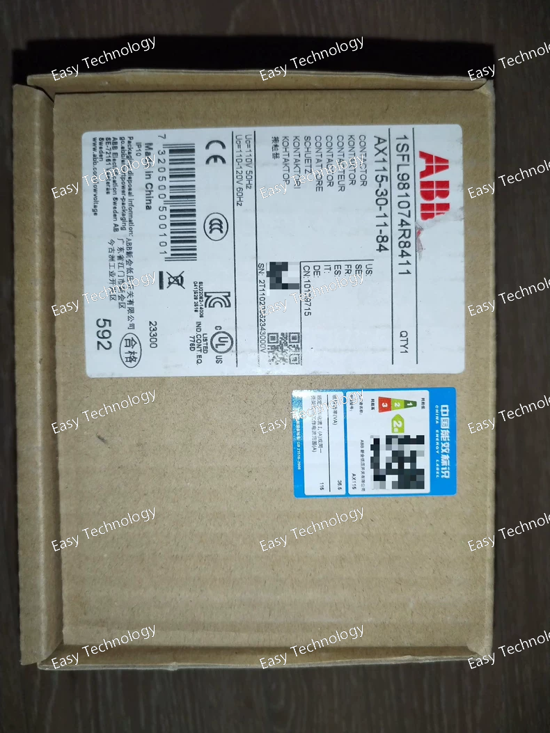
Technical Specifications Parameter Value Series / Model AX115‑30‑11‑84 Poles (Main Contacts) 3‑pole (3 Normally Open main contacts) Auxiliary Contacts 1 NO + 1 NC (Normally Open + Normally Closed) Control (Coil) Voltage (Uc) 110 V AC 50 Hz or 110–120 V AC 60 Hz Rated Main Circuit Voltage Up to 1000 V AC Conventional Free‑air Thermal Current (Ith) 160 A Rated Operational Current AC‑1 (Ie) 160 A @ 690 V (40 °C) 145 A @ 690 V (55 °C) 130 A @ 690 V (70 °C) Rated Operational Current AC‑3 (Ie) 115 A @ 380–415 V 100 A @ 440–500 V 82 A @ 690 V Rated Operational Power AC‑3 (Pe) 59 kW @ 415–500 V 75 kW @ 690 V 55 kW @ 380–400 V 30 kW @ 220–240 V Rated Making / Breaking Capacity (AC‑3) Making: 10 × Ie Breaking: 8 × Ie Short-time Withstand Current (Icw) 1 s → 1320 A; 10 s → 800 A; 1 min → 350 A; 15 min → 160 A; 30 s → 500 A Rated Insulation Voltage (Ui) 690 V Impulse Withstand Voltage (Uimp) 8 kV Maximum Electrical Switching Frequency 300 cycles/hour Maximum Mechanical Switching Frequency 3600 cycles/hour Mechanical Durability ~10,000,000 operations
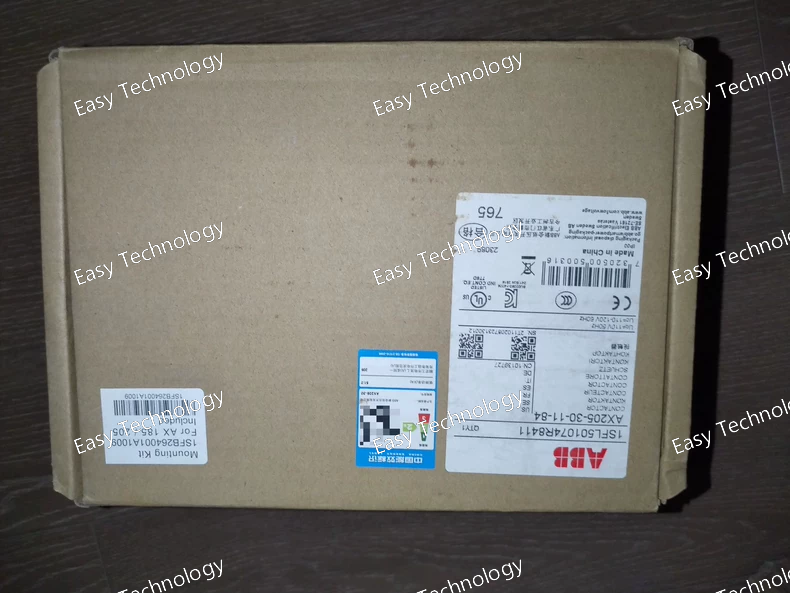
Technical Specifications Parameter Value Product Type / Model AX205‑30‑11‑84 Poles (Main Contacts) 3 poles, 3 NO (Normally Open) main contacts Auxiliary Contacts 1 NO + 1 NC (Normally Open + Normally Closed) Control (Coil) Voltage (Uc) 110 V AC, 50 Hz; or 110–120 V AC, 60 Hz Rated Main Circuit Voltage Up to 1000 V AC Conventional Free‑air Thermal Current (Ith) 250 A Rated Operational Current AC‑1 (Ie) 275 A at 690 V (40 °C) 250 A at 690 V (55 °C) 180 A at 690 V (70 °C) Rated Operational Current AC‑3 (Ie) 205 A (at 380–415 V) 185 A (440 V) 170 A (500–690 V) Rated Operational Power (AC‑3, Pe) 110 kW at 415 V / 380–400 V 90 kW at 440 V 110 kW at 500 V 132 kW at 690 V 59 kW at 220–240 V Rated Insulation Voltage (Ui) 690 V Impulse Withstand Voltage (Uimp) 8 kV Rated Making / Breaking Capacity (AC‑3) Breaking: 8 × Ie AC‑3 Making: 10 × Ie AC‑3 Short‑time Withstand Current (Icw) 1 s → 1800 A; 10 s → 1200 A; 1 min → 600 A; 15 min → 280 A; 30 s → 800 A Mechanical Durability 5,000,000 operations Maximum Mechanical Switching Frequency 3600 cycles/hour Maximum Electrical Switching Frequency 300 cycles/hour Dimensions (W × D × H) 111.5 mm × 162.3 mm × 196 mm Net Weight ≈ 3.2 kg Connection Terminals (Main Circuit) Bar contacts / main bars Ambient Temperature (with thermal overload relay) –25 °C … +55 °C Ambient Temperature (without overload relay) / Storage –40 °C … +70 °C
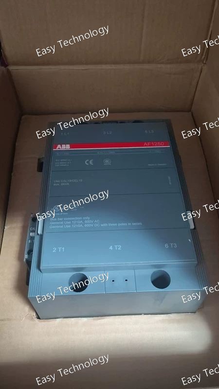
Technical Specifications Parameter Value Poles (main contacts) 3‑pole (3 Normally Open main contacts) Auxiliary contacts 1 Normally Open (NO) + 1 Normally Closed (NC) Control (coil) voltage (Us) 48–130 V AC 50/60 Hz or 48–130 V DC (for 48‑130 V version) Alternatively 100–250 V AC/DC (for 100‑250 V version) Main circuit rated operational voltage Up to 1000 V (IEC) / 600 V (UL) Rated operational current (AC‑1, 400 V) 1260 A UL general‑use current rating 1210 A Connection type (main circuit) Screw connection (main bars) Coil actuation type AC/DC
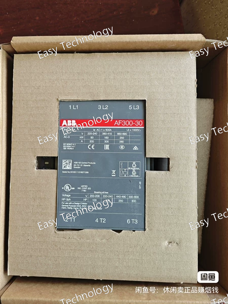
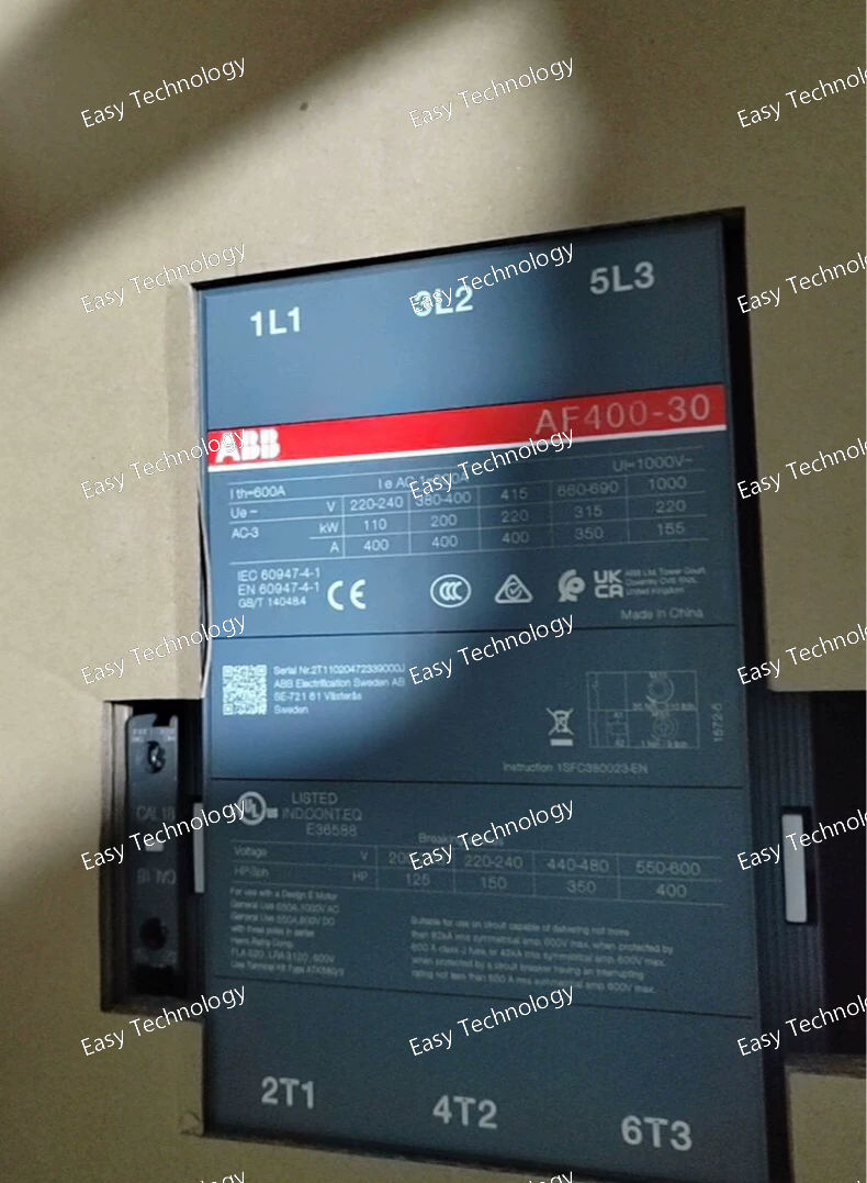
Technical Parameters Parameter / Feature Specification / Detail Model / Type AF300‑30‑11 (3‑pole contactor) Main Contacts (Power Poles) 3 × Normally‑Open (3NO) Auxiliary Contacts 1 × Normally‑Open (NO) + 1 × Normally‑Closed (NC) Rated Main-Circuit Voltage (Ue) Up to 690 V AC (nominal industrial supply) Rated Frequency (Main Circuit) 50 / 60 Hz Conventional Free‑air Thermal Current (Ith) 500 A (at 40 °C, free‑air) Rated Operational Current – AC‑1 (Ie, general load) 500 A @ 690 V (at 40 °C) Derated: 400 A @ 55 °C, 325 A @ 70 °C Rated Operational Current – AC‑3 (Ie, motor load) ~ 300 A @ 415 V (at 55 °C) ~ 280 A @ 440–500 V ~ 280 A @ 690 V (at 55 °C) Rated Motor / Load Power – AC‑3 (Pe) • ~ 90 kW @ 220–240 V • ~ 160 kW @ 380–415 V • ~ 200 kW @ 500 V • ~ 250 kW @ 690 V Making / Breaking Capacity – AC‑3 Making: 10 × Ie; Breaking: 8 × Ie Short-Time Withstand / Inrush Current (Icw) Example: 2400 A for 10 s (cold state) Control (Coil) Voltage Wide-range coil variants: 100–250 V AC / DC (50/60 Hz), or other Uc per ordering code Insulation / Withstand Ratings Insulation voltage Ui ~1000 V; Impulse withstand voltage Uimp ~8 kV Terminals / Connections Main circuit: bar/bus‑bar type terminals (for heavy cables or busbars) Auxiliary: screw-type terminals Mechanical / Electrical Endurance High endurance for heavy-duty switching; suitable for frequent operation cycles Typical Applications Three-phase motor start/stop, industrial machinery control, heavy load switching, power distribution panels, motor‑control centres, large AC load switching.
Technical Parameters Parameter / Feature Specification / Detail Model / Type AF260‑30‑11 (3‑pole AC contactor) Main Contacts 3 × Normally‑Open (NO) Auxiliary Contacts 1 × NO + 1 × NC Control (Coil) Voltage 100–250 V AC/DC, 50/60 Hz Rated Operational Voltage (Main Circuit) Up to 690 V AC Conventional Free‑air Thermal Current (Ith) 400 A (at 40 °C) Rated Operational Current AC‑1 (Ie) 400 A @ 690 V (40 °C); 350 A @ 55 °C; 290 A @ 70 °C Rated Operational Current AC‑3 (Motor Load) 260 A @ 415 V; 240 A @ 440–500 V; 220 A @ 690 V Rated Motor / Load Power AC‑3 (Pe) ~ 140 kW @ 415/440 V; ~ 180 kW @ 500 V; ~ 200 kW @ 690 V Making / Breaking Capacity (AC‑3) Making: 10 × Ie; Breaking: 8 × Ie Short‑time Withstand Current (Icw) 2400 A at 690 V for 10 s Rated Insulation Voltage (Ui) 1000 V Impulse Withstand Voltage (Uimp) 8 kV Terminals / Connections Bar‑type main terminals; screw‑type auxiliary terminals Mechanical / Electrical Endurance ~ 5 million mechanical operations Typical Applications Motor start/stop control, industrial machinery, heavy 3‑phase loads, power distribution panels
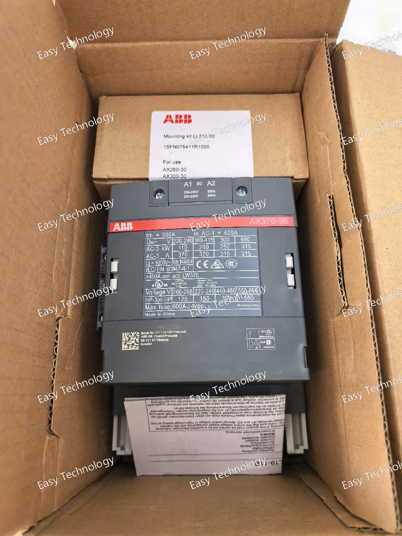
Technical Parameters Parameter / Feature Specification / Detail Model / Type AX370‑30‑11‑80 (3‑pole contactor) Main Contacts / Poles 3 poles — 3 × Normally‑Open (NO) main contacts Auxiliary Contacts 1 × Normally‑Open (NO) + 1 × Normally‑Closed (NC) auxiliary contact block Control (Coil) Voltage 220–230 V AC (50 Hz) or 230–240 V AC (60 Hz) Rated Operational Voltage (Main Circuit) Up to 1000 V AC (insulation rating) / nominal use up to 690 V AC AC‑1 Rated Operational Current (Ie) 600 A @ 690 V (at 40 °C ambient) 500 A @ 690 V (at 55 °C) 400 A @ 690 V (at 70 °C) AC‑3 Motor Duty Current (Ie) 370 A @ 380–440 V (55 °C) 315 A @ 500–690 V (55 °C) AC‑3 Rated Motor Power (Pe) ~ 200 kW at 415–440 V ~ 250 kW at 500 V ~ 315 kW at 690 V Short‑time Withstand / Inrush Current (Icw) – 2960 A for 10 s (from cold) – 3700 A for 1 s (cold state) Other short‑time ratings per spec sheet Making / Breaking Capacity (AC‑3) Making: 10 × Ie; Breaking: 8 × Ie Rated Insulation Voltage (Ui) 690 V (according to IEC 60947‑4‑1) Impulse Withstand Voltage (Uimp) 8 kV Frame / Design Block‑type 3‑pole contactor with built‑in auxiliary contact block Terminals / Connection Type Main circuit: bar / busbar‑type terminals (heavy‑duty) Auxiliary circuit: screw‑terminals Mechanical Endurance ~ 5 million mechanical operations Max Switching Frequency Up to 300 switching cycles/hour (electrical/mechanical) Ambient / Operating Conditions With thermal overload relay: –25 °C … +55 °C; Without overload relay: –40 °C … +70 °C Suitable up to 3000 m altitude without derating Typical Applications Large 3‑phase motor start/stop, heavy‑load switching, industrial machinery, power distribution panels, motor‑control centres, large AC load control
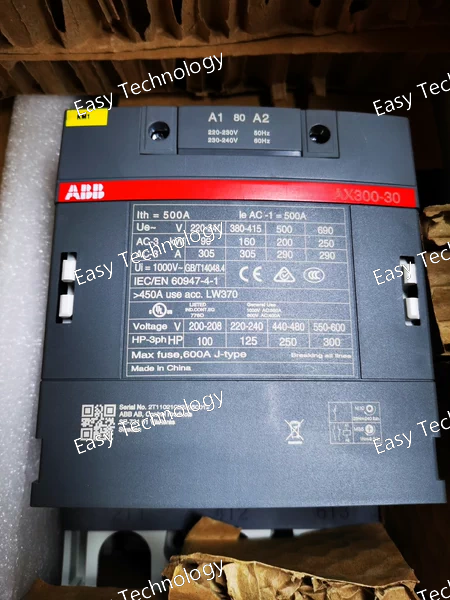
Technical Parameters Parameter / Feature Specification / Detail Model / Type AX300‑30‑11 — 3‑pole AC contactor Main Contacts (Power) 3 × Normally‑Open (NO) contacts (3P) Auxiliary Contacts 1 × Normally‑Open (NO) + 1 × Normally‑Closed (NC) auxiliary contact block Rated Operational Voltage (Main Circuit) Up to 1000 V (IEC insulation rating) — nominally up to ~690 V AC for typical use Conventional Free‑air Thermal Current (Iₜₕ) 250 A (at 40 °C, open contactor) Rated Operational Current, AC‑1 (General Load) Up to 500 A @ 690 V (40 °C), derating to 400 A @ 55 °C or 325 A @ 70 °C Rated Operational Current, AC‑3 (Motor Load) • 305 A @ 415–440 V • 290 A @ 500–690 V (at 55 °C) Rated Motor / Load Power, AC‑3 (Pₑ) • 160 kW @ 415 / 440 V • 200 kW @ 500 V • 250 kW @ 690 V • 90 kW at 220–240 V AC Making / Breaking Capacity (AC‑3) Making capacity: 10 × Ie; Breaking capacity: 8 × Ie (per IEC 60947‑4‑1) Short‑Time / Withstand / Inrush Current Ratings e.g. 10 s withstand: ~ 2440 A; 1 s: ~ 3050 A; other ratings per spec sheet depending on ambient & conditions Rated Frequency (Main Circuit) 50 / 60 Hz Control/Coil Voltage Variants Multiple coil‑voltage variants available (e.g. 220‑230 V AC, 110 V AC, 24 V AC/DC depending on order code) Terminal / Connection Type Bar‑type / busbar‑type main terminals (suitable for heavy cabling or busbars); screw‑type auxiliary‑contact terminals Mechanical Durability / Endurance Approx. 5 million mechanical operations (heavy‑duty rating) Typical Applications Three‑phase motor start/stop control; large motor switching; heavy‑load control; industrial machinery; power distribution panels; heavy‑duty AC load switching
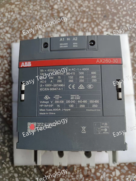
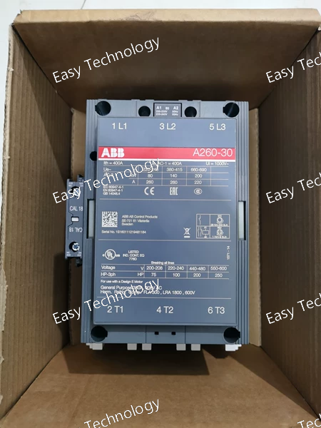
Technical Parameters Parameter / Feature Specification / Detail Series / Model AX260‑30 Main Contacts 3 × Normally‑Open (NO) Auxiliary Contacts 1 × NO + 1 × NC Rated Main-Circuit Voltage (Ue) Up to 690 V AC Conventional Free-air Thermal Current (Ith) 250 A at 40 °C Rated Operational Current AC‑1 (Ie) 400 A @ 690 V (derated 350 A @ 55 °C, 290 A @ 70 °C) Rated Operational Current AC‑3 (Ie, motor load) 265 A @ 400–415 V; 250 A @ higher voltages up to 690 V Rated Motor / Load Power (AC‑3) ~132 kW @ 415 V; ~160 kW @ 440–500 V; ~200 kW @ 690 V Coil / Control Voltage Multiple variants (e.g., 110 V AC, 220–230 V AC) depending on ordering code Making / Breaking Capacity (AC‑3) Making capacity: 10 × Ie; Breaking capacity: 8 × Ie Terminals / Connection Type Main: bar-type for heavy cables/busbars; Auxiliary: screw-type Mechanical / Electrical Endurance Up to 5 million mechanical operations Typical Applications Three-phase motor start/stop, industrial motor control, general power circuits, heavy-load control, power distribution panels
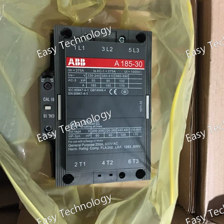
Technical Parameters Parameter / Feature Specification / Detail Model / Type A185‑30‑11 3‑Pole AC Contactor Poles / Main Contacts 3 × Normally‑Open (NO) — three‑phase main circuit Auxiliary Contacts 1 × NO + 1 × NC (for control/signalling) Rated Main‑Circuit Voltage (Ue) Up to 690 V AC (IEC‑rated) Conventional Free‑air Thermal Current (I_th) 275 A at 40 °C (free‑air) Rated Operational Current (AC‑1, Ie) 275 A @ 690 V (40 °C); derated to 250 A @ 55 °C; 180 A @ 70 °C Rated Motor‑Switching Current (AC‑3, Ie) 185 A @ 400–415 V AC; 170 A @ 500–690 V AC (typical) Rated Motor / Load Power (AC‑3) Up to ~ 90 kW at 400 V; ~ 132 kW at 690 V (depending on load & supply) Coil / Control Supply Voltage Versions available (e.g. 110–120 V AC coil; other coil‑voltages depending on variant) Rated Insulation Voltage (Ui) 1000 V (IEC standard insulation rating) Impulse Withstand Voltage (Uimp) 8 kV (main contacts) Mechanical Endurance ~ 5 million switching operations Connection / Terminals Screw‑type terminals; main contacts via heavy‑duty bars/busbars Protection / Enclosure Rating (terminals) Coil terminals: IP20; main terminals: IP00 (open bar type) Typical Use Cases 3‑phase motor start/stop; industrial load switching; motor control panels; power distribution; contactor‑based machine control

Technical Parameters / Key Specifications Parameter / Feature Specification / Detail Model / Type A110‑30‑00‑80 (ABB A‑Line series contactor) Number of Poles 3‑pole (3P), 3 main contacts (3 NO) Auxiliary Contacts None (no auxiliary contacts on this variant) Coil / Control Voltage 230–240 V AC (50/60 Hz) Main‑Circuit Rated Voltage Up to 1000 V AC (IEC insulation rating) / suitable nominally for 690 V AC industrial supply Conventional Free‑air Thermal Current (Ith) 160 A (at 40 °C, free air) Rated Operational Current, AC‑1 (Ie, general load) 160 A (at 40 °C); derated with higher ambient temperature (e.g. 145 A @ 55 °C; 130 A @ 70 °C) Rated Operational Current, AC‑3 (Ie, motor load) ~110 A (at typical 400–415 V load) Motor / Load Capability (Example) Up to ~ 40 HP at 230/240 V 1‑phase; up to ~ 75 HP at 460/480 V 3‑phase; higher ratings at higher voltages, depending on application Mounting / Terminals DIN‑rail or panel mount; screw‑type terminals (for main contacts) Design / Safety Features Touch‑safe terminal design; block‑type contactor housing; standard industrial IEC/UL/CSA compliance Typical Applications 3‑phase motor start/stop control; load switching; general industrial power circuits; contactor‑based panel control; non‑reversing applications where no auxiliary contacts are required
Technical Parameters Parameter / Feature Specification / Detail Model / Type AF460‑30‑11 (3‑pole AC/DC contactor) Main Contacts 3 × Normally‑Open (NO) main contacts Auxiliary Contacts 1 NO + 1 NC auxiliary contact block Rated Operational Voltage (Main Circuit) Up to 1000 V AC (IEC insulation rating) / 690 V AC nominal for many usages Conventional Free‑air Thermal Current (Ith) 700 A @ 40 °C free air (derates with higher ambient temperature) Rated Operational Current AC‑1 (Ie, general load) 700 A @ 690 V (40 °C); derated to e.g. 600 A @ 55 °C, 480 A @ 70 °C Rated Operational Current AC‑3 (Ie, motor load) ~ 460 A @ 415–500 V AC; 400 A @ 690 V AC; (dependent on ambient and wiring) Rated Operational Power — AC‑3 Up to ~ 250 kW @ 400 V; ~ 315 kW @ 500 V; ~ 355 kW @ 690 V (for motor loads) Making/Breaking Capacity (AC‑3) Making capacity up to 10 × Ie; Breaking capacity up to 8 × Ie (per IEC 60947‑4‑1) Coil / Control Supply Voltage (Uc) Wide coil‑voltage variants: e.g. 100–250 V AC/DC standard; other variants also available by ordering code Rated Frequency (Main Circuit) 50 / 60 Hz AC Utilization / Duty Categories AC‑1 (general load), AC‑3 (motor switching), suitable for high-power applications Insulation & Withstand Ratings Rated insulation voltage Ui = 1000 V; Impulse withstand voltage Uimp ≈ 8 kV Terminals / Connection Capacity Main‑circuit bar‑type terminals (suitable for heavy conductors / busbars); auxiliary screw‑type terminals Mechanical Durability / Endurance ~ 3,000,000 switching cycles (or as specified per version) — robust for long‑term industrial use Typical Applications Large motor start/stop, industrial machinery control, heavy‑load switching, electrical distribution panels, bypass/isolation circuits, three‑phase load control
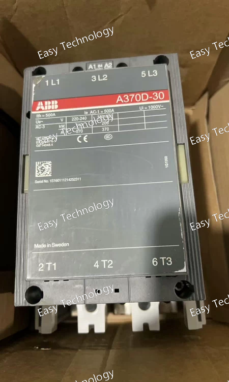
Technical Parameters Parameter / Feature Specification / Detail Model / Type A370D‑30‑11 (3‑pole AC contactor) Poles / Main Contacts 3 poles — 3 × Normally‑Open (NO) Auxiliary Contacts 1 × NO + 1 × NC Rated Operational Voltage (Main Circuit) Up to 690 V AC Conventional Free-air Thermal Current (Ith) 600 A at 40 °C Rated Operational Current — AC‑1 600 A @ 690 V (derated 500 A @ 55 °C, 400 A @ 70 °C) Rated Operational Current — AC‑3 370 A @ 380–415 V; 350 A @ 500 V; 315 A @ 690 V Maximum Motor Power (AC‑3) Up to 315 kW depending on voltage & load conditions Coil / Control Voltage Multiple variants (AC or DC) depending on ordering code Terminals / Connections Bar-type main terminals for heavy cables/busbars; screw-type auxiliary terminals Mechanical / Electrical Endurance Designed for industrial heavy-duty use; high cycle life Insulation / Impulse Withstand Voltage Ui = 1000 V; Uimp ≈ 8 kV Standards IEC 60947‑4‑1 compliant Operating Conditions Ambient temperature –25 °C … +50 °C (with overload relay); –40 °C … +70 °C (without overload relay) Typical Applications Three-phase motor control, heavy load switching, industrial machinery, power distribution panels, load isolation/bypass
 TEL: Grace +86 13600179521
  Mail: info@hongkongeasy.com jilineasyyi@outlook.com
 Q Q:615739355
 ADDRESS:Unit 12, 20th Floor, Good View Commercial Centre, 2-16 Garden Street, Mong Kok, Hong Kong
 whats app


