
Industrial Controller
All product are in stock,guaranteed delivery within 3-7 days.


PRODUCT
PICTURE
BRAND
DESCRIBE
STOCK
DOWNLOAD
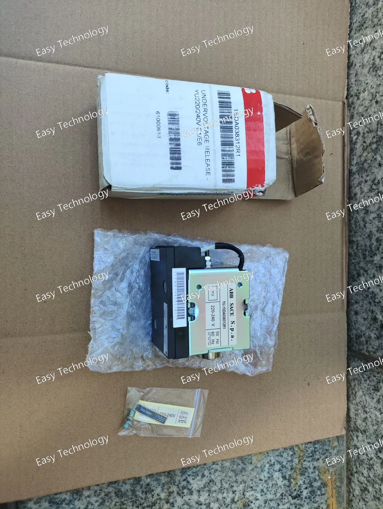
Specifications General Product Type: Shunt Opening Release / Shunt Trip Part Number: 1SDA038286R1 Manufacturer: ABB Applicable Breakers: ABB Emax (E1, E2, E3, E4, E6, T8) Function Provides remote electrical tripping of the circuit breaker Activated by supplying control voltage to the release coil Suitable for automated control and protection systems Electrical Characteristics Rated Control Voltage: 24 V DC Control Type: Direct-current shunt trip coil Operation: Opens breaker immediately upon energizing Mechanical / Compatibility Designed to mount inside designated accessory slot on ABB Emax breakers Compatible with multiple frame sizes (E1–E6 and T8) Suitable for both new installations and retrofit upgrades Compliance Designed per IEC standards for breaker accessories CE compliant RoHS compliant Typical Applications Remote trip from PLC or DCS Fire alarm system shutdown Emergency stop circuits Electrical interlocking Energy management systems requiring remote breaker control
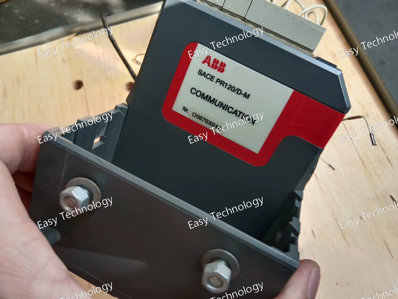
Specifications Protection Functions (Protection levels depend on breaker configuration) Long-time protection (L) Adjustable overload protection with programmable pickup and delay. Short-time protection (S) Adjustable pickup and delay with I²t ON/OFF. Instantaneous protection (I) Adjustable magnetic trip for short-circuit protection. Neutral protection (N) (when neutral CT or module is installed) Note: PR122/D-M supports standard protection suite of PR122/D series; ground-fault “G” protection requires the respective version (not included in D-M). Metering & Measurement (M – Metering Function) Phase currents Neutral current (with module) Ground current indication Voltage values (with voltage module) Power & energy (kW, kWh, kVA, kVAR) Frequency Power factor Thermal capacity Trip history & events Display & Operation Large multifunction LCD display Local pushbuttons for settings and navigation LED indicators for status and alarms Adjustable Settings L – Long-time pickup & delay S – Short-time pickup & delay, I²t enabled/disabled I – Instantaneous pickup setting N – Neutral protection (optional) Supported Current Ratings Compatible with Emax/Emax2 breakers rated: 160 A – 6300 A, depending on frame size and CT rating. Accuracy Current measurement: typically ±1% Voltage & power measurement (with module): high accuracy per IEC standards Tripping characteristics compliant with IEC 60947-2 Communication (Optional) Supports ABB communication modules such as: Modbus Profibus DeviceNet Ethernet gateways (via expansion) Enables remote settings, monitoring, and event logs. Power Supply Self-powered via CTs Optional auxiliary power depending on configuration Compliance IEC 60947-1 IEC 60947-2 CE and international approvals (breaker-dependent)
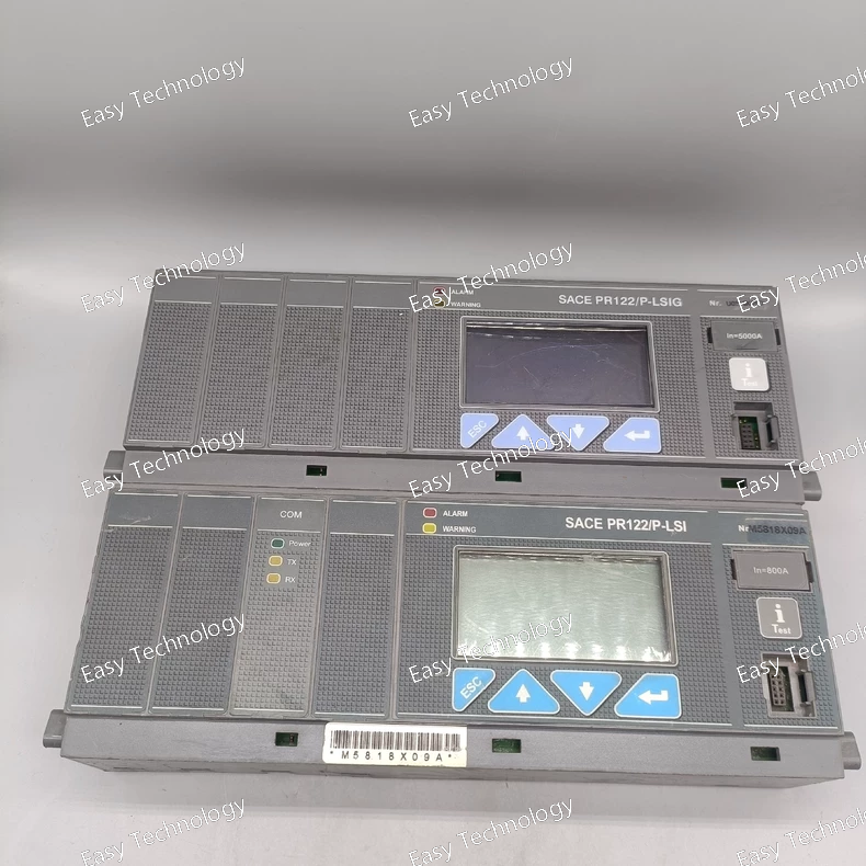
Specifications Protection Functions L – Long-time protection Adjustable pickup (typically 0.4–1 × In) and time delay for overload protection. S – Short-time protection Adjustable pickup and time delay with I²t or fixed delay selection. I – Instantaneous protection Adjustable magnetic trip for short-circuit fault clearing. G – Ground-fault protection Adjustable pickup and delay to protect against ground-fault currents. Measurement & Monitoring Measures: Phase currents Neutral current (with module) Ground-fault current Thermal capacity Trip history & alarms Digital LCD display for settings and real-time data. Adjustable Settings L (Long-time): Pickup & delay adjustable S (Short-time): Pickup & delay adjustable; I²t ON/OFF I (Instantaneous): Adjustable trip threshold G (Ground-fault): Pickup & delay adjustable Supported Rated Currents Works with Emax/Emax2 breakers from In 160A – 6300A (depends on breaker frame) Accuracy Current measurement accuracy: typically ±1% Protection tripping accuracy per IEC standards Display & Interface Multifunction LCD display LED status indicators Front pushbuttons for settings navigation Communication (optional) Compatible with ABB communication modules (Modbus, Profibus, DeviceNet, etc.) Event logging and remote supervision when communication enabled Power Supply Self-powered from current sensors (CT-fed), auxiliary power optional depending on configuration. Standards Compliance IEC 60947-1 IEC 60947-2 CE and international certifications (breaker dependent) Installation Plug-in module for ABB Emax/Emax2 air circuit breakers Field-replaceable trip unit
Key Parameters Parameter Specification Product Type 3-Pole AC Magnetic Contactor Series / Family A-Line (A95) Frame Size/Type Code A95-30-11 Rated Operational Current 95 A (main contacts) Poles 3 Phase 3-phase Control / Coil Voltage 110–120 VAC (50/60 Hz, typical) – variations available Rated Operational Voltage (Main Circuit) Up to ~600 V AC (depending on variant / configuration) Control Frequency 50/60 Hz Auxiliary Contacts 1 NO + 1 NC (typical for “-30-11” configuration) Mounting Type Panel or DIN-rail (depending on accessory/variant) Application Motor control, switching loads, isolation Standards Compliance IEC/EN contactor standards (e.g., IEC 60947-4-1) Typical Utilization Motor starters, control circuits, industrial distribution Construction AC magnetic contactor with replaceable auxiliary contacts
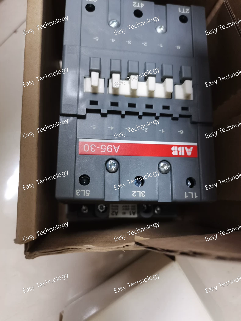
Key Parameters Parameter Specification Product Type 3-Pole AC Magnetic Contactor Series / Family A-Line (A95) Frame Size/Type Code A95-30-11 Rated Operational Current 95 A (main contacts) Poles 3 Phase 3-phase Control / Coil Voltage 110–120 VAC (50/60 Hz, typical) – variations available Rated Operational Voltage (Main Circuit) Up to ~600 V AC (depending on variant / configuration) Control Frequency 50/60 Hz Auxiliary Contacts 1 NO + 1 NC (typical for “-30-11” configuration) Mounting Type Panel or DIN-rail (depending on accessory/variant) Application Motor control, switching loads, isolation Standards Compliance IEC/EN contactor standards (e.g., IEC 60947-4-1) Typical Utilization Motor starters, control circuits, industrial distribution Construction AC magnetic contactor with replaceable auxiliary contacts
Technical Specifications Parameter Value / Description Model / Part Number AF460‑30‑11 (1SFL597001R7011) Poles (Main Contacts) 3 poles, 3 NO (normally open) Auxiliary Contacts 1 NO + 1 NC Coil (Control) Voltage (Uc) 100–250 V AC 50/60 Hz or 100–250 V DC (depending coil version) Rated Insulation / Maximum Rated Voltage Up to 1000 V IEC (600 V UL) Conventional Free‑air Thermal Current (Ith) 700 A (open contactor, ambient 40 °C) Rated Operational Current AC‑1 (Ie) 700 A @ 1000 V, 40 °C 600 A @ 1000 V / 55 °C 600 A @ 1000 V / 60 °C 480 A @ 1000 V / 70 °C (equivalently at 690 V: 700 A → 600 A → 480 A depending on temperature) Rated Operational Current AC‑3 (Ie) 460 A @ 415–500 V (55 °C) 400 A @ 690 V (55 °C) 200 A @ 1000 V (55 °C) 460 A @ 380/400 V or 220–240 V (55 °C) Rated Operational Power (AC‑3, Pe) 250 kW @ 415–440 V 315 kW @ 500 V 355 kW @ 690 V 280 kW @ 1000 V 250 kW @ 380/400 V 132 kW @ 220–240 V Making / Breaking Capacity (AC‑3) Making: 10 × Ie Breaking: 8 × Ie Short‑time Withstand Current (Icw) (cold start, free air, 40 °C) 1 s → 4600 A 10 s → 4400 A 30 s → 3100 A 1 min → 2500 A Connection Type (Main Circuit) Bar-type main contacts (supports rigid copper or aluminium cables/bars) Auxiliary & Coil Terminal Wiring Capacity Aux circuit: flexible cables with ferrules 2×0.75–2.5 mm², or solid/stranded 1–4 mm² Main circuit: rigid Cu 240 mm² or Al 2×240 mm² bar Ambient Operating Temperature With thermal overload relay: –25 °C … +50 °C Without overload relay: –40 °C … +70 °C Storage: –40 °C … +70 °C Maximum Operating Altitude Up to 3000 m Certifications / Use Cases UL/CSA general‑use rating: 650 A @ 600 V AC; suitable for motor starters, power switching, bypass/distribution, heavy‑duty switching
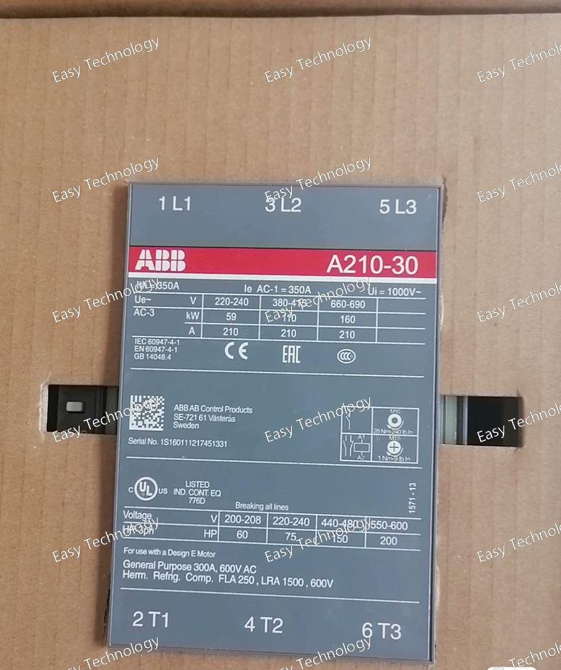
Technical Specifications Parameter Value / Description Series / Frame AF210‑30 Poles (Main Contacts) 3 poles, 3 NO (normally open) Auxiliary Contacts 1 NO + 1 NC Coil (Control) Voltage U<sub>c</sub> 100–250 V AC 50/60 Hz or 100–250 V DC Rated Main‑Circuit Voltage up to 690 V AC Conventional Free‑air Thermal Current (I<sub>th</sub>) 350 A (open contactor, 40 °C) Rated Operational Current AC‑1 (I<sub>e</sub>) 350 A @ 690 V (40 °C); 300 A @ 690 V (55 °C); 240 A @ 690 V (70 °C) Rated Operational Current AC‑3 (I<sub>e</sub>) 210 A @ 415/440/500/690 V (55 °C) (also 210 A at 380/400 V or 220–240 V) Rated Power (AC‑3, P<sub>e</sub>) 59 kW @ 220–240 V; 110 kW @ 380–415/440 V; 132 kW @ 500 V; 160 kW @ 690 V Main‑circuit connection / terminal type Bar‑type main contacts (suitable for rigid Cu or Al cable or bus bars) Mechanical endurance / durability ~5,000,000 mechanical cycles Size / Dimensions (approx.) Width 140 mm × Depth 180.5 mm × Height 227 mm Ambient Operating Temperature With thermal overload relay: –25 °C … +55 °C; Without overload relay: –40 °C … +70 °C Insulation / Rated Insulation Voltage (U<sub>i</sub>) 1000 V (IEC standard), 600 V (UL/CSA) Auxiliary circuits wiring Auxiliary circuit terminals: flexible 1–4 mm² or solid cables; main circuits support large cross‑section bars/cables
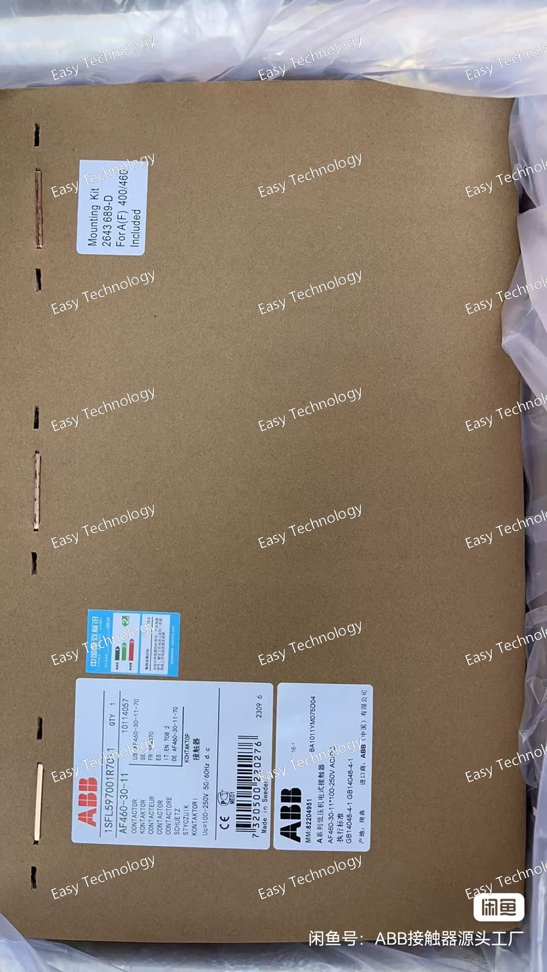
Technical Specifications Parameter Value / Description Model / Series / Part Number AF460‑30‑11 — 1SFL597001R7011 Poles (Main Contacts) 3 poles, 3 NO (normally open) Auxiliary Contacts 1 NO + 1 NC Coil (Control) Voltage (Uc) 100–250 V AC 50/60 Hz or 100–250 V DC Main Circuit Rated Operational Voltage Up to 1000 V IEC / 600 V UL Conventional Free‑air Thermal Current (Ith) 700 A (open contactor, 40 °C, per IEC 60947‑4-1) Rated Operational Current AC‑1 (Ie) 700 A @ 1000 V / 40 °C 600 A @ 1000 V / 55 °C 600 A @ 1000 V / 60 °C 480 A @ 1000 V / 70 °C Equivalent 700 A → 600 A → 480 A @ 690 V (various ambient temps) Rated Operational Current AC‑3 (Ie) 460 A @ 415–500 V (55 °C) 400 A @ 690 V (55 °C) 200 A @ 1000 V (55 °C) Rated Operational Power AC‑3 (Pe) 250 kW @ 400–415 V 315 kW @ 500 V 355 kW @ 690 V (at 1000 V rating: 280 kW) Making / Breaking Capacity AC‑3 Making capacity: 10 × Ie Breaking capacity: 8 × Ie Short-time Withstand Current (Icw) From cold state (free air, 40 °C): – 1 s: 4600 A – 10 s: 4400 A – 30 s: 3100 A – 1 min: 2500 A Main Circuit Connection / Terminal Type Bar‑type main circuit bars; supports large rigid Cu or Al cables / bars (e.g. 240 mm² rigid Cu, 2×240 mm² Al) Coil Terminal / Auxiliary Circuit Connection Auxiliary circuit: flexible cables with ferrules (2 × 0.75–2.5 mm²) or solid/stranded 1–4 mm² Mechanical / Electrical Endurance / Use Cases Designed for heavy‑duty three‑phase motor control, switching power circuits, motor starters, bypass/distribution, isolation, etc. Ambient Temperature (Operating) With thermal overload relay: –25 °C … +50 °C Without additional relay: –40 °C … +70 °C Storage: –40 °C … +70 °C Max Altitude for Use Up to 3000 m Misc Features Built‑in surge suppression; wide coil voltage tolerance; modular block‑type design with accessory expansion capability; suitable for use with add‑on auxiliary contact blocks, overload relays, etc.
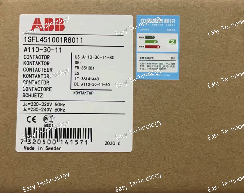
Technical Specifications Parameter Value Model / Series A110‑30‑11 (Frame: A110) Poles (Main Contacts) 3 poles, 3 NO (Normally Open) Auxiliary Contacts 1 NO + 1 NC Coil (Control) Voltage (typical) 110–120 V AC (there are also variants with different coil voltages) Rated Operational Voltage (Main Circuit) Up to 1000 V (depending on variant) Conventional Free‑air Thermal Current (Ith) 160 A @ 40 °C Rated Operational Current AC‑1 (Ie) 160 A @ 690 V (at 40 °C) 145 A @ 690 V (at 55 °C) 130 A @ 690 V (at 70 °C) Rated Operational Current AC‑3 (Ie) ~110 A @ 380–415 V ~100 A @ 440–500 V ~82 A @ 690 V Rated Operational Power AC‑3 (Pe) 55 kW @ 380–400 V 59 kW @ 415–440/500 V 75 kW @ 690 V Insulation / Voltage Rating (Ui) Up to 1000 V (IEC standard) / 600 V (UL/CSA) UL/CSA General‑Use Rating 140 A @ 600 V AC Auxiliary Contact Terminals & Main Circuit Terminals Screw / Cable‑clamp type Ambient Temperature (Operating) With thermal overload relay: –25 °C … +50 °C (or –25 °C … +55 °C depending coil) Without overload relay: –40 °C … +70 °C Typical Dimensions Approx. 148 mm (H) × 102 mm (W) × 123.5 mm (D) Typical Max Motor Load Capacities (UL/CSA) 3‑phase motor up to 75 hp @ 480 V, 100 hp @ 600 V (depending wiring/conditions)
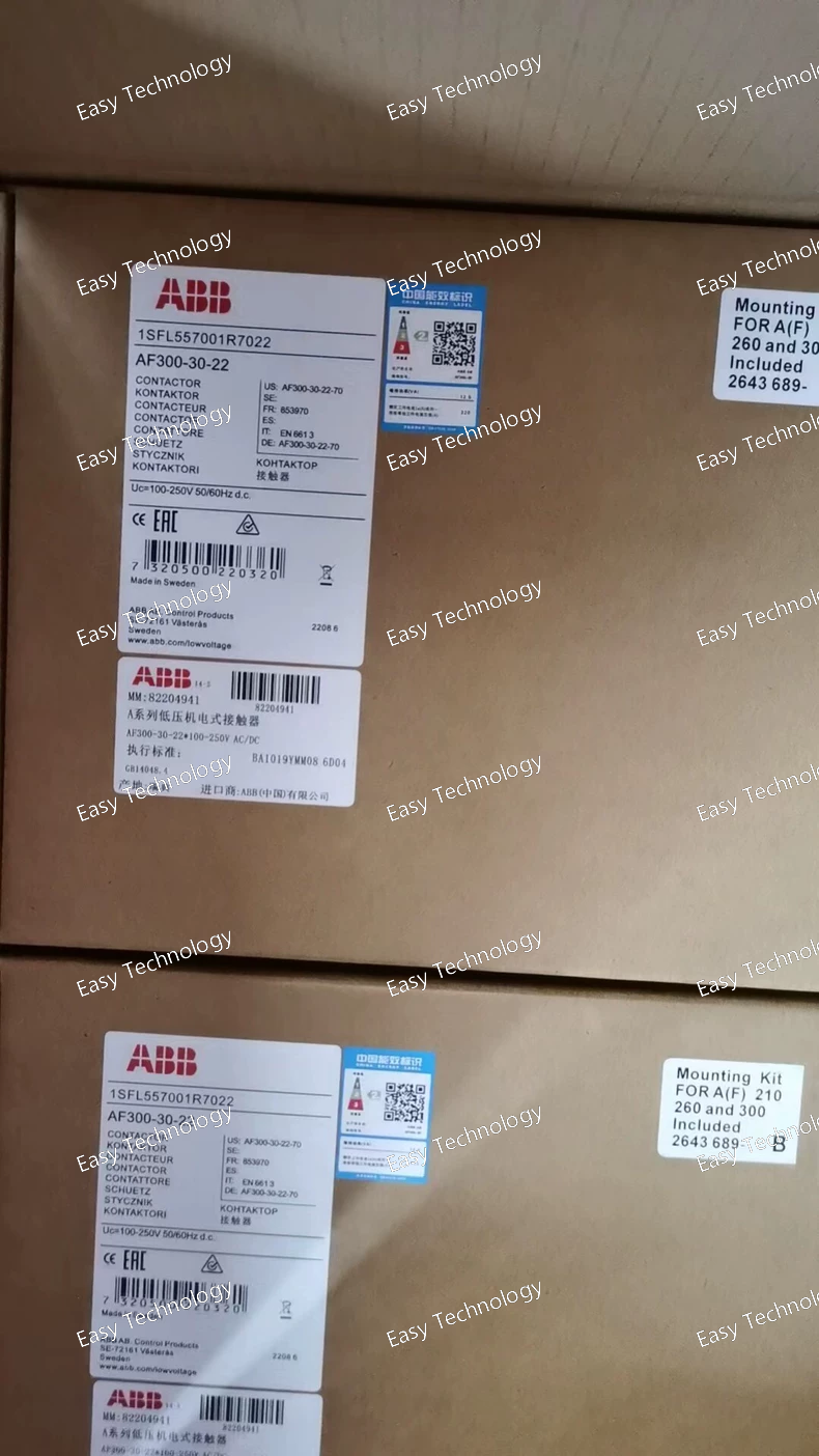
Technical Specifications Parameter Value / Description Model / Series AF300‑30‑22 Contact Configuration (Main) 3 poles, 3 NO (3‑phase main contacts) Auxiliary Contacts 2 NO + 2 NC (on certain sub‑types) — depending on coil version Coil (Control) Voltage (Uc) Various coil‑voltage options depending on version (e.g. 48–130 V AC/DC, or 100–250 V AC/DC depending on coil code) Max Insulation / Rated Main‑Circuit Voltage Up to 690 V AC (main circuit) Rated Operational Current (AC‑1, Ith) 500 A (in free air under reference conditions) Typical Rated Operational Current (AC‑1, Ie) Up to 500 A at 690 V (depending on ambient temp and load) Typical Rated Operational Current (AC‑3, Ie) ~305 A (depending on voltage and sub‑type) Rated Power (AC‑3, Pe) E.g. for 690 V operation, up to ~250 kW (depends on load and coil version) Making / Breaking Capacity (AC‑3) Making: 10 × Ie Breaking: 8 × Ie (per IEC 60947‑4-1 standard) Short‑time Withstand Current (Icw) From cold state in free air: 1 s → ~3500 A; 10 s → ~2400 A; 30 s or specified durations depend on sub‑type / specs Terminals / Connection Type Bar‑type main contacts (suitable for rigid Cu or Al cables / bars) Mechanical / Electrical Endurance Mechanical durability rating typical for AF‑series heavy‑duty contactors (designed for frequent switching)
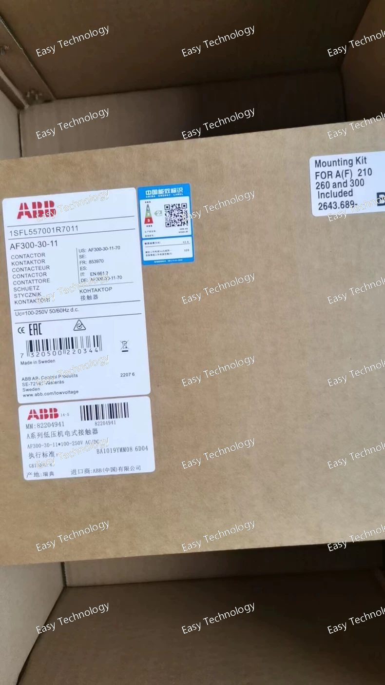
Technical Specifications Parameter Value Model / Series AF300‑30‑11‑70 Contact Configuration (Main) 3 poles, 3NO Auxiliary Contacts 1 NO + 1 NC Coil (Control) Voltage 100–250 V AC/DC, 50/60 Hz Main Circuit Rated Voltage Up to 690 V AC Conventional Free‑air Thermal Current (Ith) 500 A Rated Operational Current AC‑1 (Ie, 690 V) 500 A @ 40 °C; 400 A @ 55 °C; 325 A @ 70 °C Rated Operational Current AC‑3 (Ie) 220–240 V: 305 A; 380–400 V: 305 A; 415 V: 300 A; 440–500 V / 690 V: 280 A Rated Operational Power AC‑3 (Pe) 220–240 V: 90 kW; 380–400 V: 160 kW; 415–440 V: 160 kW; 500 V: 200 kW; 690 V: 250 kW Making / Breaking Capacity (AC‑3) Making: 10 × Ie ; Breaking: 8 × Ie Short-time Withstand Current (Icw) 1 s → 3500 A; 10 s → 2400 A; 15 min → 500 A Terminals / Connection Type Screw terminals (main and auxiliary) Dimensions (W × D × H) 140 × 180.5 × 227 mm Ambient Operating Temperature With thermal overload relay: –25 °C … +50 °C; Without overload relay: –40 °C … +70 °C
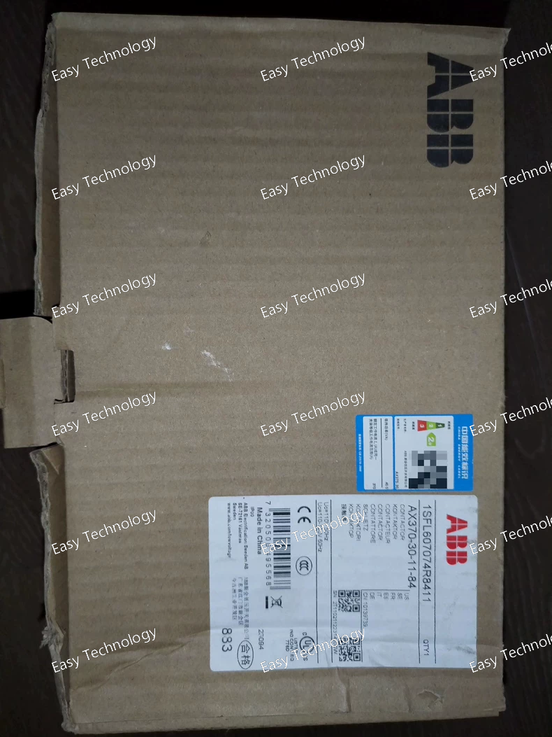
Technical Specifications Parameter Value Model / Part Number AX370‑30‑11‑84 Poles (Main Contacts) 3‑pole (3 Normally Open) Auxiliary Contacts 1 NO + 1 NC Control (Coil) Voltage (Uc) 110 V AC 50 Hz or 110–120 V AC 60 Hz Rated Main Circuit Voltage Up to 1000 V AC Conventional Free‑air Thermal Current (Ith) 250 A Rated Operational Current AC‑1 (Ie) 600 A @ 690 V (40 °C) 500 A @ 690 V (55 °C) 400 A @ 690 V (70 °C) Rated Operational Current AC‑3 (Ie) 370 A @ 415–440 V / 380–400 V / 220–240 V 315 A @ 500–690 V Rated Operational Power AC‑3 (Pe) 200 kW @ 415–400 V 250 kW @ 500 V 315 kW @ 690 V 110 kW @ 220–240 V Making / Breaking Capacity (AC‑3) Making: 10 × Ie Breaking: 8 × Ie Short‑time Withstand Current (Icw) 1 s → 3700 A; 10 s → 2960 A; 1 min → 1208 A; 15 min → 600 A Rated Insulation Voltage (Ui) 690 V Impulse Withstand Voltage (Uimp) 8 kV Maximum Electrical Switching Frequency 300 cycles/hour Maximum Mechanical Switching Frequency 300 cycles/hour Degree of Protection (Auxiliary Terminals) IP40 Terminal Type (Main Circuit) Bar-type terminals Ambient Air Temperature (with thermal overload relay) –25 °C … +55 °C Ambient Air Temperature (without overload relay / storage) –40 °C … +70 °C
 TEL: Grace +86 13600179521
  Mail: info@hongkongeasy.com jilineasyyi@outlook.com
 Q Q:615739355
 ADDRESS:Unit 12, 20th Floor, Good View Commercial Centre, 2-16 Garden Street, Mong Kok, Hong Kong
 whats app


