
Industrial Controller
All product are in stock,guaranteed delivery within 3-7 days.


PRODUCT
PICTURE
BRAND
DESCRIBE
STOCK
DOWNLOAD
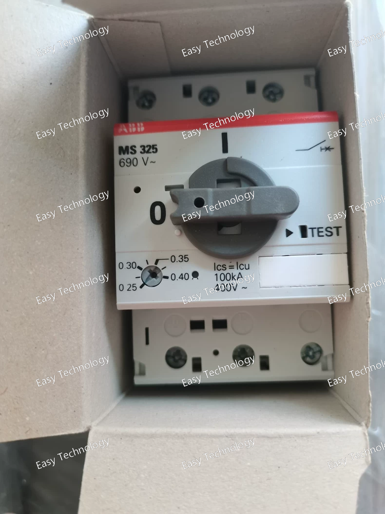
Specifications General Product Type: Manual Motor Starter / Manual Motor Protector Series: MS325 Model: MS325‑0.4 Rated Operational Current: ~0.4 A (with adjustable setting range typically from ~0.25 A to 0.4 A) Number of Poles: 3‑pole (three‑phase protection) Manual Control: Rotary handle with ON/OFF indication Electrical Rated Operational Voltage (Main Circuit): Up to 690 V AC Rated Control Frequency: 50/60 Hz Thermal Overload Protection: Integrated thermal‑magnetic trip element Trip Class: Class 10A (time‑current tripping characteristic), providing overload protection Short‑Circuit Protection: Trip‑free mechanism to interrupt fault current quickly Phase Loss Protection: Yes (protects against phase failure/imbalance) Disconnect Function: Yes (isolates motor circuit when OFF) Motor Ratings: Suitable for motors up to ~0.4 A FLA (approx. ~2.4 A LRA at low voltage) across three‑phase systems per standard motor rating tables used by this series. Mechanical & Performance Handle Type: Manual rotary handle Enclosure Protection: IP20 (standard for panel installation) Mounting: Panel/DIN‑rail compatible Operating Cycles: Around 50,000 electrical and 100,000 mechanical cycles typical for starter class devices Trip‑Free Mechanism: Yes (prevents holding ON under fault conditions) Phase Compensation: Yes (temperature and phase imbalance compensation included) Physical Compact Design: Suitable for space‑constrained control panels Connection Terminals: Screw terminals Approximate Dimensions: Standard small‑starter size (~54 mm width typical for MS325 range) Weight: Lightweight design (compact starter) Environmental Operating Ambient Temperature: –25 °C to +50 °C (typical industrial ambient range) Storage Temperature: Standard industrial storage range Pollution Degree: Suitable for typical industrial panel environments Altitude: Up to typical installation altitudes (without derating) Typical Applications Manual start/stop and overload protection for small three‑phase motors HVAC systems, small pumps, fans, compressors Machine tool motor protection Conveyor and light industrial applications Control panels requiring motor protection without separate fuses
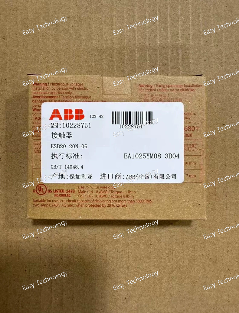
Specifications General Product Name: Installation Contactor Model / Part Number: ESB20‑20N‑06 Series: ESB20..N Poles: 2 Main Contacts: 2 NO, 0 NC Modular Width: 18 mm (1 module) Weight: ~0.14 kg Protection Rating: IP20 Mechanical Endurance: ~1,000,000 cycles Electrical Endurance: ~150,000 switching cycles under rated conditions Operating Ambient Temperature: –25 °C to +55 °C Storage Temperature: –40 °C to +80 °C Maximum Operating Altitude: Up to ~2000 m Pollution Degree: 3 Electrical Ratings – Main (Load) Circuit Rated Operational Voltage: 250 V AC, 220 V DC Rated Operational Current (AC‑1, Ie): 20 A Rated Operational Current (AC‑3, Ie): 9 A @ 230 V Rated Operational Power (AC‑1): ~4.6 kW @ 230 V Rated Operational Power (AC‑3): ~1.3 kW @ 230 V Rated Insulation Voltage (Ui): 400 V Rated Impulse Withstand Voltage (Uimp): 6 kV Control Circuit Rated Control Voltage (Uc): 230 V AC/DC Control Frequency: 50 Hz / 60 Hz (up to 400 Hz for control circuit) Terminals & Wiring Main Circuit Connection Capacity: • Flexible up to 6 mm² • Rigid up to 10 mm² Control Circuit Connection Capacity: • Flexible 0.75–2.5 mm² • Rigid 0.5–4 mm² Tightening Torque: • Main ~1.2 N·m • Control ~0.9 N·m Stripping Length: ~7 mm Standards & Compliance Designed according to IEC/EN 60947‑1 and IEC/EN 60947‑4‑1 Suitable for low‑voltage distribution and control panels in residential, commercial, and industrial environments Typical Applications Switching and control of single‑phase loads: • Lighting circuits • Heaters and water heaters • Ventilation fans and blowers • Pump motors and small drives • Modular distribution board control logic
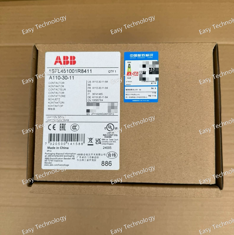
Specifications General Product Name: AC Power Contactor Model / Part Number: 1SFL451001R8411 Series: A110 (A‑Series) Type: 3‑Pole Contactor Application: Motor control, power switching, distribution panels Mounting: DIN‑rail or panel mount compatible Auxiliary Contacts: 1 NO + 1 NC Control / Coil Rated Control Voltage: 110 V AC (50 Hz) / 110–120 V AC (60 Hz) Coil Type: AC coil for direct control supply Main Circuit Ratings Rated Operational Voltage: Up to 1000 V AC (main circuit) Rated Operational Current: AC‑1: 160 A AC‑3: 110 A (at 400 V) Inductive Load Current: 110 A Rated Power (AC‑3): ~55 kW @ 400 V AC ~30 kW @ 230 V AC ~75 kW @ 690 V AC Rated Breaking Capacity: 8 × Ie (AC‑3) Rated Making Capacity: 10 × Ie (AC‑3) Rated Insulation Voltage (Ui): ~1000 V AC Rated Impulse Withstand Voltage (Uimp): ~8 kV Contact Configuration Main Contacts: 3 normally open (3 NO) Auxiliary Contacts: 1 normally open + 1 normally closed Performance Mechanical Endurance: High cycle life for frequent operation Switching Frequency: AC‑1: ~300 cycles/hour AC‑3/AC‑4: ~150–300 cycles/hour Mechanical: ~3600 cycles/hour Short‑Time Withstand Current: ~800 A (10 s) ~350 A (1 min) Mechanical & Physical Number of Poles: 3 Connection Type: Cable clamp terminals Weight: ~2.0 kg Compact Block Design: Suitable for modular motor control assemblies Environmental Operating Temperature: –40 °C to +70 °C Storage Temperature: –60 °C to +80 °C Maximum Operating Altitude: Up to ~3000 m Standards & Compliance Complies with IEC/EN standards for contactors and motor starters Suitable for industrial power control applications Typical Applications Motor starters in industrial control panels Power distribution switching HVAC and pump control systems Bypass and isolation switching Integration with overload relay and automation logic
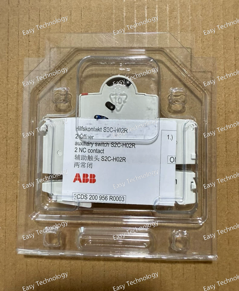
Specifications General Product Name: Auxiliary Contact Block Model / Part Number: S2C‑H02R (10120503) Accessory Type: Auxiliary contact for miniature circuit breakers Mounting Position: Right‑side mount on breaker Compatible With: ABB S‑series MCBs and compatible RCDs in the S‑range Contact Arrangement Contacts: 2 auxiliary contacts Operation: Simultaneous switching with breaker actuation for status signaling Contact Function: Provides open/closed indication of breaker position Electrical Ratings Rated Insulation Voltage (Ui): Up to 400–500 V AC (standard auxiliary voltage rating) Rated Operational Voltage: Up to 250–400 V AC (auxiliary circuits) Rated Frequency: 50 Hz / 60 Hz Rated Operational Current: Low control currents typical for auxiliary/indicator circuits Suitable for PLC/automation inputs, alarm circuits, and signal lamps Mechanical Mounting: Clip‑on accessory that attaches to the right side of the breaker Connection: Screw terminals for field wiring Terminal Wire Size: Suitable for small control wire (e.g., 0.5–2.5 mm²) Compact Design: Minimal added width to the breaker assembly Performance & Environment Contact Durability: Designed for frequent auxiliary switching in control logic Ambient Temperature: Standard electrical distribution board conditions Pollution Degree: Rated for typical commercial/industrial panel environments Protection: IP20 at terminals Applications Breaker status indication: Remote ON/OFF/TRIP signals Control logic: Interface with PLC, BMS, or automation systems Alarm circuits: Remote alarm indication Interlocking: Use in safety or interlock schemes where breaker status is required
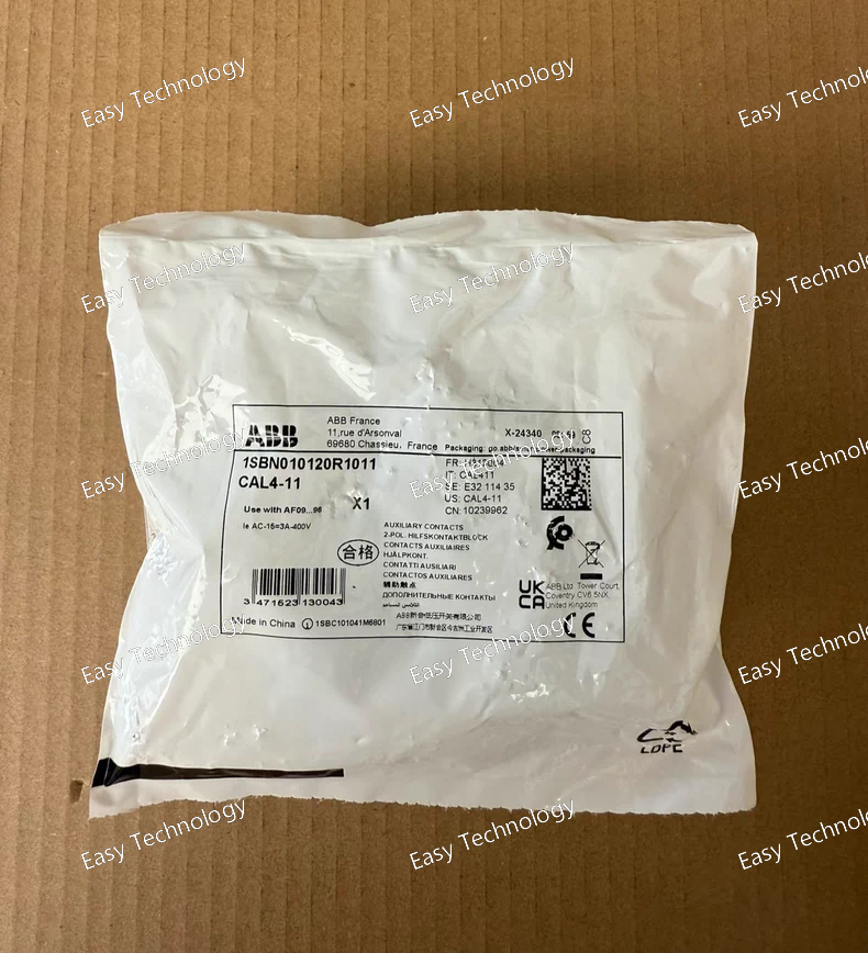
Specifications General Product Name: Auxiliary Contact Block Model / Part Number: 1SBN010120R1011 (CAL4‑11) Accessory Type: Side‑mounted auxiliary contact block Compatible With: ABB AF and NF series contactors and relays Mounting Position: Side mount on contactor or relay Contact Arrangement Contacts: 1 NO + 1 NC Operation: Instantaneous auxiliary switching Electrical Ratings Rated Insulation Voltage (Ui): Up to 690 V AC Rated Operational Voltage: 24 V … 690 V AC Rated Frequency: 50 Hz / 60 Hz Rated Operational Current (AC‑15): 6 A @ 24/127 V AC 4 A @ 220/240 V AC 3 A @ 400/440 V AC 2 A @ 500/690 V AC Rated Operational Current (DC‑13): 6 A @ 24 V DC 0.55 A @ 110–125 V DC 0.27 A @ 220–250 V DC Conventional Free‑air Thermal Current (Ith): ~16 A at 40 °C Mechanical & Performance Screw Terminal Connections: Yes Mechanical Switching Frequency: ~3600 cycles/hour Electrical Switching Frequency: AC‑15: ~1200 cycles/hour DC‑13: ~900 cycles/hour Impulse Withstand Voltage (Uimp): ~6 kV Rated Short‑time Withstand Current: 140 A (0.1 s) 100 A (1 s) Physical Mounting Type: Side clipping on contactor body Terminal Type: Screw terminals Wire Size: 0.75 – 2.5 mm² Tightening Torque: ~1.2 N·m Protection Rating: IP20 at terminals Dimensions (approx): 12 mm (W) × 60 mm (D) × 69 mm (H) Weight: ~0.04 kg Applications Status feedback for contactor position (open/closed) Control interlocks in motor starters Signal logic in control panels and automation systems Extra auxiliary switching functions for safety and sequencing
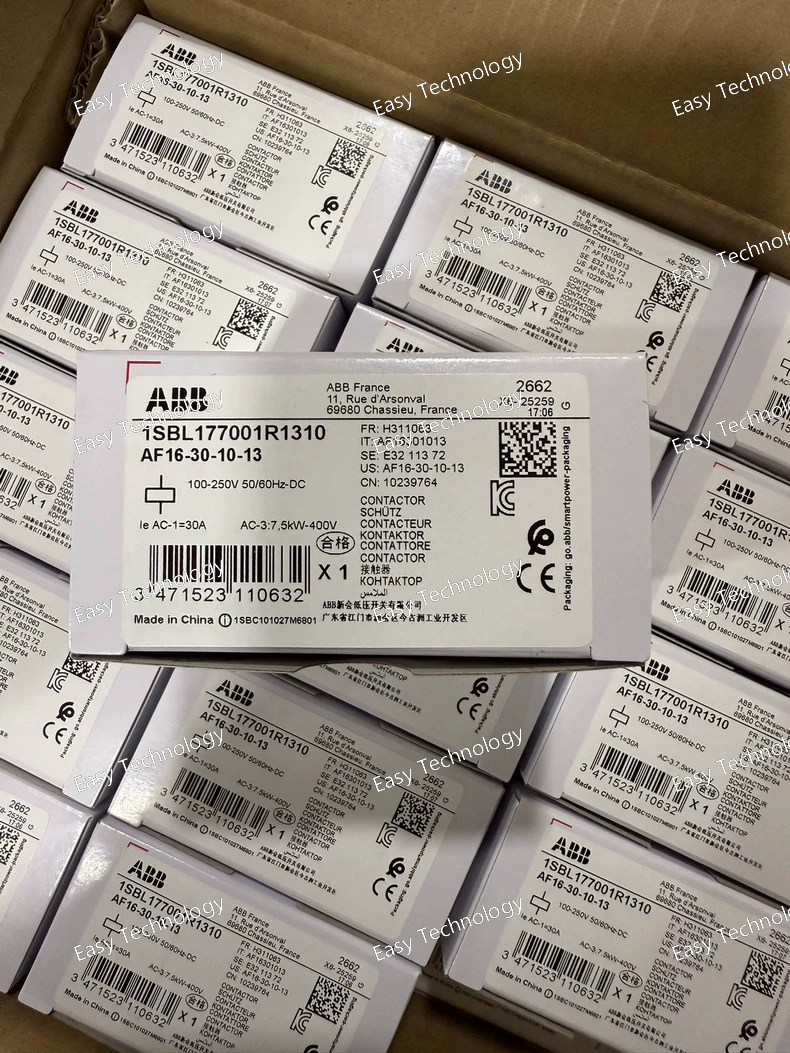
Specifications General Product Name: AF16‑30‑10‑13 AC Contactor Model / Part Number: 1SBL177001R1310 Series: AF16 (ABB AF contactor family) Application: Switching of three‑phase motors and power loads Main Poles: 3 (three‑phase) Auxiliary Contacts: 1 normally open (NO) built‑in auxiliary contact Mounting: Panel or DIN‑rail compatible block design Terminal Type: Screw terminals Protection Class: IP20 Control (Coil) Control Voltage Range: 100–250 V AC, 50/60 Hz and 100–250 V DC Coil Type: AC/DC wide‑range coil Surge Protection: Built‑in for improved performance with voltage variations Electrical Ratings Rated Operational Voltage (Main Circuit): Up to 690 V AC Rated Operational Current (AC‑1): 30 A at 690 V Rated Operational Power (AC‑3): ~4 kW @ 220–240 V AC ~7.5 kW @ 380–400 V AC ~9 kW @ 415–500 V AC Rated Insulation Voltage (Ui): 690 V AC (IEC) / 600 V AC (UL/CSA) Dielectric / Impulse Withstand Voltage: ~6 kV Maximum Breaking Capacity: ~250 A @ 440 V AC ~106 A @ 690 V AC Rated Control Circuit Frequency: 50/60 Hz Performance Mechanical Endurance: High cycle life suitable for frequent switching Electrical Endurance: Designed for industrial load switching duties Operating Time (Coil → Contact): ~38–95 ms (energize); ~11–98 ms (de‑energize) Rated Operational Current (DC‑13): Various ratings depending on DC voltage (e.g., ~6 A @ 24 V, ~0.55 A @ 125 V, ~0.27 A @ 250 V) Mechanical & Physical Dimensions: Approx. 45 mm (W) × 86 mm (H) × 77 mm (D) Weight: ~0.27 kg Connection Capacity: Main: 1–6 mm² conductors Control/Auxiliary: 0.75–2.5 mm² conductors Operating Altitude: Up to ~3000 m without derating Environmental Operating Ambient Temperature: Without overload: ~−40 °C to +70 °C With thermal overload relay: ~−25 °C to +60 °C Storage Temperature: ~−60 °C to +80 °C Standards & Compliance IEC 60947‑1 / 60947‑4‑1 UL 508 CSA C22.2 No.14 Designed for industrial contactor and motor control applications Typical Applications Three‑phase motor starters Industrial automation panels Power distribution control HVAC and pump control systems Integration with overload relays and PLC logic
pecifications General Product Name: Auxiliary Contact Model / Part Number: S2C‑H11L (2CDS200936R0001) Accessory Type: Auxiliary contact block for miniature circuit breakers Mounting Position: Left side of the MCB Suitable For Breakers: ABB S200, S200M, S200P, S200S, S200 MT, S200 MUC, S300P Contact Arrangement: 1 Normally Open (NO) + 1 Normally Closed (NC) Function: Provides breaker status indication / signalling Electrical Ratings Maximum Power Loss: 1 W (maximum) Contact Switching Ratings (typical categories): AC‑14: ~1 A @ 400 V AC, ~2 A @ 230 V AC DC‑12: ~1 A @ 220 V DC, ~1.5 A @ 110 V DC DC‑13: ~2 A @ 60 V DC, ~4 A @ 24 V DC Electrical Performance: Designed to reliably switch auxiliary/control currents for status signalling Mechanical Dimensions: Width: ~8.8 mm Height: ~85 mm Depth: ~69 mm Weight: ~0.04 kg Construction: Compact block‑type for easy mounting and wiring Environmental & Compliance RoHS Compliant: Yes, meets EU environmental directives Operating Conditions: Standard ambient conditions for distribution board environments Installation: Suitable for electrical distribution, control cabinets, and monitoring systems Typical Applications Remote indication of breaker ON/OFF/TRIP status Integration with control systems (PLC, BMS, SCADA) for status feedback Electrical panel signalling and interlocking logic Enhanced breaker feedback for automation and safety systems
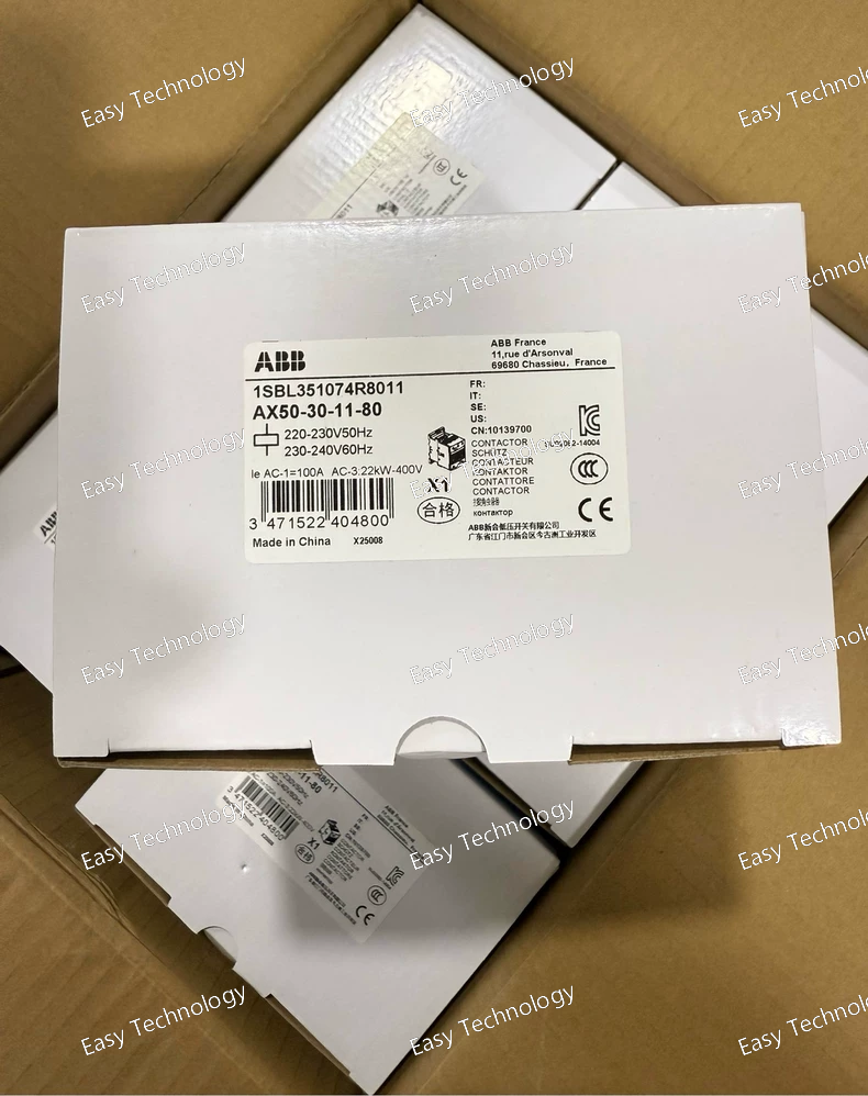
Specifications General Product Name: Industrial AC Power Contactor Model / Part Number: 1SBL351074R8011 Series: AX50 Application: Switching and control of three‑phase motors and power loads Mounting: DIN‑rail / panel mount Main Poles: 3 Electrical Ratings Coil Voltage: 220–230 V AC, 50 Hz / 230–240 V AC, 60 Hz Rated Operational Voltage (Ue): Up to 690 V AC Rated Operational Current: • AC‑3 (motor duty): ~50 A @ 415 V AC • AC‑1 (general use): ~85–100 A Rated Power (AC‑3 motor duty): ~25 kW @ 415 V AC, ~30 kW @ 500–690 V AC, ~15 kW @ 220–240 V AC Contacts Main Contacts: 3 NO (normally open) poles Auxiliary Contacts: 1 NO + 1 NC Contact Utilization: Suitable for AC‑3 motor loads and general AC switching Performance Conventional Free‑air Thermal Current (Ith): ~100 A Mechanical Endurance: Up to 10 million operating cycles Electrical Endurance: Rated for frequent load switching at specified AC ratings Mechanical Poles: 3 Dimensions (approx): 108 mm H × 82 mm W × 110 mm D Weight: ~1.05–1.16 kg Terminal Type: Screw terminals Protection Class: IP20 Environmental Operating Temperature: –40 °C to +70 °C Storage Temperature: –60 °C to +80 °C Maximum Operating Altitude: Up to 3000 m without derating Standards & Compliance Designed per IEC 60947‑4‑1 for contactors and motor starters Suitable for industrial motor control and power switching Typical Applications Three‑phase motor starters Industrial automation panels Power distribution contact switching HVAC and pump control systems Integration with overload relays and control logic
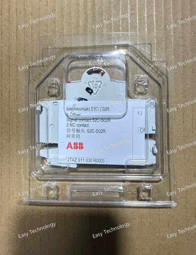
Specifications General Product Name: Signal Contact Accessory Part Number: S2C‑S02R (10134809) Accessory Type: Signal contact (auxiliary accessory for breaker status indication) Mounting Position: Right side mount onto compatible breakers Suitable Devices: Miniature Circuit Breakers (S200, S200M, S200P), Residual Current Devices (RCDs F200, DS200), Switch Disconnectors Installation: Add‑on accessory that clips onto the breaker body Electrical Ratings Rated Insulation Voltage (Ui): ~400 V AC Rated Impulse Withstand Voltage (Uimp): ~4 kV Conventional Free‑Air Thermal Current (Ith): ~10 A Utilization Categories: AC‑12: ~3 A @ 400 V AC / ~2 A @ 230 V AC AC‑14: ~1 A @ 400 V AC / ~2 A @ 230 V AC DC‑12/DC‑13: Up to ~4 A @ 24 V DC / ~2 A @ 60 V DC Minimum Operational Current/Voltage: ~10 mA @ 12 V / ~5 mA @ 24 V Contacts & Function Contact Function: Signal contact indicating breaker status (e.g., trip) Contact Configuration: Typically SPDT (signal only; not main breaker switching) Signal Output: Provides feedback to external control or alarm circuits Mechanical Dimensions (approx): Height ~85 mm × Width ~8.9 mm × Depth ~67–69 mm Weight: ~0.04 kg Mounting: Snap‑on or slide‑on accessory fitting onto right side of breaker accessory slot Connection Terminals: Screw terminals compatible with wiring for control or signal circuits Performance & Environmental Operating Temperature: Standard electrical panel ambient range Pollution Degree: Suitable for typical distribution board environments Vibration & Shock: Designed for reliable contact stability in control and distribution systems Standards & Safety Standards Compliance: Meets applicable auxiliary contact and low‑voltage accessory standards used in modular breaker accessory designs Protection Class: IP20 across terminals and accessory body Applications Status Feedback: Remote indication of breaker trip/open/closed state Control Interlocking: Integration with automation, alarms, or building management systems Panel Monitoring: Provides signal to PLCs, indicator lights, or supervisory systems Safety Systems: Used where breaker condition must be reported for safety or maintenance logic
Specifications General Product Name: CR‑MX230AC4L Pluggable Interface Relay Part Number: 1SVR405633R3100 Series: ABB CR‑MX miniature relay series Type: Electromechanical interface relay Mounting: Pluggable into socket/base for control panel installation Control / Coil Rated Control Supply Voltage: 230 V AC Coil Type: AC coil Coil Indicator: Integrated LED to indicate coil energization Contact / Output Contact Configuration: 4 C/O (4 changeover) SPDT contacts Contact Material: Silver alloy Rated Operational Voltage (Ue): Up to 250 V AC Rated Operational Current: 5 A @ 250 V AC (general resistive load) Minimum Switching Voltage: 5 V Minimum Switching Current: 5 mA Utilization Category: AC‑12 Resistive, AC‑15 Inductive loads Performance Mechanical Life: ≥ 2×10⁷ switching cycles Electrical Life (AC‑1): ≥ 1×10⁵ cycles Response Time: ≤ 20 ms Release Time: ≤ 25 ms (AC coil) Electrical Ratings Maximum Switching Voltage: 250 V AC / 110 V DC Maximum Switching Power: AC‑1 Resistive: ~1250 VA AC‑15 Inductive: ~0.8 A @ 250 V AC Mechanical & Physical Mounting: Plug‑in interface relay base Socket Options: Compatible with dedicated CR‑MX relay sockets Isolation: Galvanic isolation between coil and contacts Polarity: Not polarity sensitive for AC coil Environmental Operating Ambient Temperature: –40 °C to +70 °C Storage Temperature: Standard industrial storage range Shock / Vibration Resistance: Designed for control‑cabinet environments Applications Logic interface between control devices and field loads PLC output signal amplification and isolation Automation control panels Switching general‑purpose low power loads
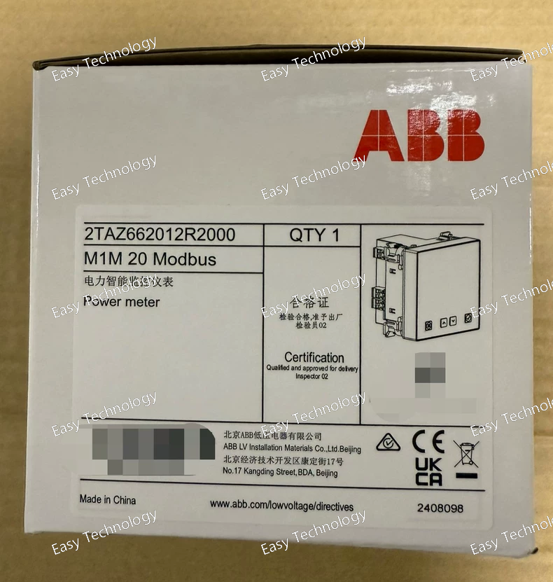
pecifications Product Identity Product Name: M1M 20 Modbus Power Meter Model / Part Number: 2TAZ662012R2000 Category: Three‑Phase Power & Energy Meter Display: LCD front‑panel display for real‑time parameter visualization Communication: Modbus RTU via RS‑485 interface Mounting: Front panel cut‑out installation (standard 96 × 96 mm) Electrical Auxiliary Supply Voltage: 100–230 V AC/DC Power Consumption: Up to ~5 VA Rated Frequency: 50/60 Hz Measurement Inputs: Voltage and current via external CTs (1 A or 5 A secondary) Phase System: Three‑phase (3P) Voltage Measurement Range: Supports standard low‑voltage systems Communication Interface: RS‑485 Modbus RTU Measured Parameters Voltage: Line‑to‑Line and Line‑to‑Neutral Current: Per phase through CTs Power: Active (kW), Reactive (kVAR), Apparent (kVA) Energy: Active and Reactive energy (kWh, kVArh) Power Factor: Per phase and total Frequency: Line frequency monitoring Harmonics / Unbalance: Optional power quality indices Communication & Integration Protocol: Modbus RTU Interface: RS‑485 Integration: PLCs, SCADA, BMS, EMS Device Addressing: Modbus standard addressing supported Mechanical & Environmental Dimensions: Front panel 96 × 96 mm Depth: Approx. 77–85 mm Weight: ~0.3–0.35 kg Protection: IP51 front, IP20 terminals Operating Temperature: Standard industrial range Termination: Screw-type terminals for power, CT, and communication Standards & Compliance Safety & EMC: Complies with relevant IEC/EN standards RoHS Compliant: Yes Typical Applications Energy monitoring in industrial facilities Power distribution boards and switchgear Integration into Building/Energy Management Systems Load profiling and electrical parameter logging Remote monitoring and alarm systems via Modbus networks
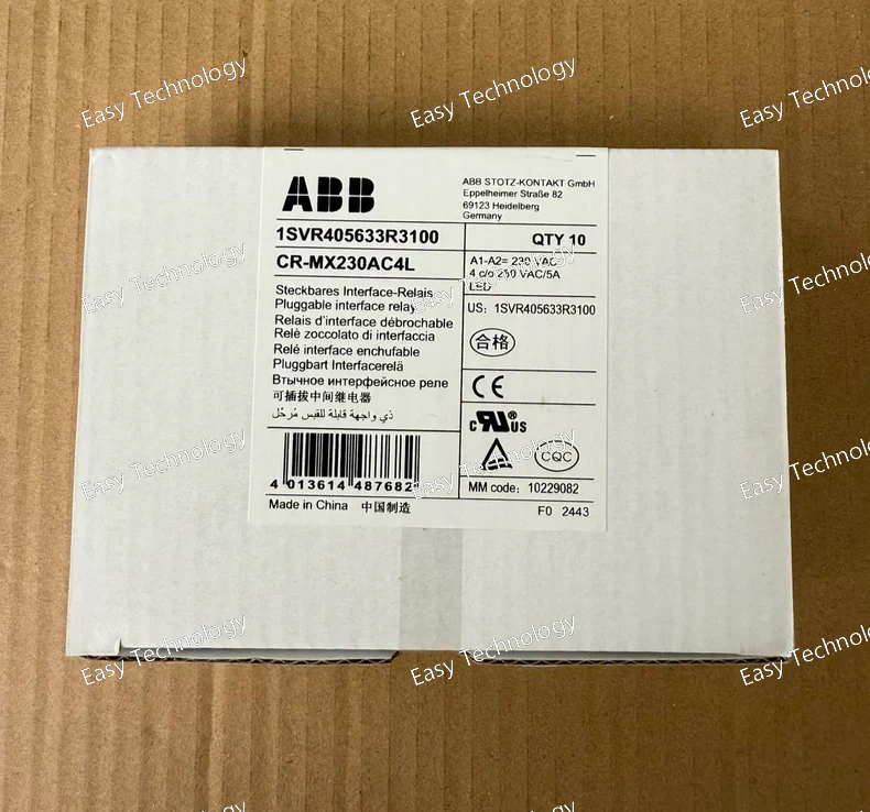
Specifications General Product Name: Pluggable Interface Relay Model / Part Number: 1SVR405633R3100 Series: CR‑MX miniature relay range Product Type: Control/Interface Relay Coil Voltage: 230 V AC LED Indicator: Yes (built‑in status LED) Mounting: Pluggable relay socket / DIN‑rail compatible Contact/Output Contact Configuration: 4 C/O (4 changeover contacts) Contact Type: SPDT (Single Pole Double Throw) Rated Load: 5 A at 250 V AC (general purpose) Contact Material: Cadmium‑free environmental type Contact Arrangement: Four independent changeover outputs for flexible switching Electrical Control Supply Voltage: 230 V AC Coil Type: AC control coil Frequency: 50/60 Hz (for mains AC control) Dielectric / Insulation: Designed for signal isolation and safe switching of control and load circuits Performance & Features Integrated LED: Indicates coil energization status Compact and Modular: Suitable for tightly spaced control panels Pluggable Design: Allows easy replacement and socket mounting No Cadmium Contacts: Environmentally friendly contact material Mechanical Pins / Terminal Style: Pluggable pins for use with matched socket or base Accessories: Compatible with relay bases, markers, and holders Environmental & Compliance Operating Temperature Range: Typical industrial ambient (standard control enclosure usage) Compliance: Meets applicable industrial control relay standards, with CE marking and other certifications Materials: Complies with REACH and RoHS environmental regulations Applications Interfacing low‑power control logic with load circuits PLC output relay replacement Automation systems Control panels for industrial machinery Switching of control and signal loads
 TEL: Grace +86 13600179521
  Mail: info@hongkongeasy.com jilineasyyi@outlook.com
 Q Q:615739355
 ADDRESS:Unit 12, 20th Floor, Good View Commercial Centre, 2-16 Garden Street, Mong Kok, Hong Kong
 whats app


