
Industrial Controller
All product are in stock,guaranteed delivery within 3-7 days.


PRODUCT
PICTURE
BRAND
DESCRIBE
STOCK
DOWNLOAD
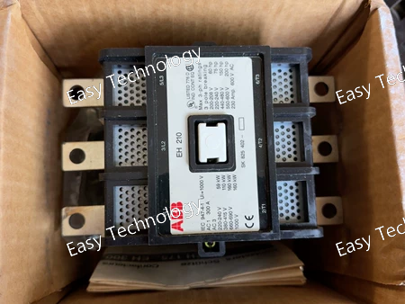
Technical Parameters Parameter Specification Product series ABB EH series contactor Poles 3 poles Main contact configuration 3 NO (Normally Open) Built-in auxiliary contacts 1 NO + 1 NC Rated operational voltage (Ue) Up to 690 V AC Rated operational current (Ie, AC-1) Approx. 275 A Rated motor power (AC-3) Up to 75 kW at 400 V Utilization category AC-1, AC-3 Control circuit voltage (coil) Typically 110–120 V AC (check coil code for exact voltage) Control voltage frequency 50 / 60 Hz Mechanical durability Up to 10 million operations Electrical durability Depends on load and utilization category Ambient operating temperature −25 °C to +55 °C Mounting Panel mounting Protection degree IP00 (IP20 with accessories) Applicable standards IEC compliant Typical applications Motor starters, MCC panels, industrial power switching
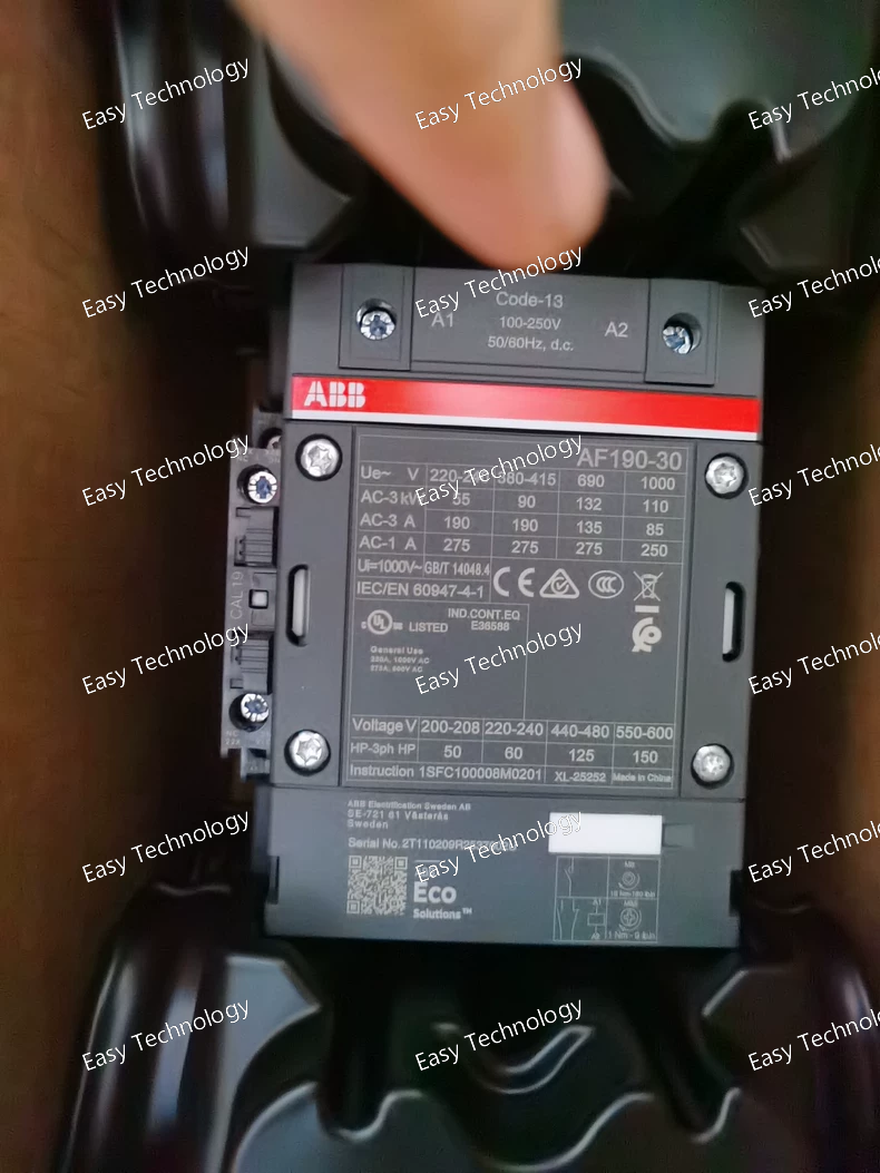
Technical Parameters Parameter Specification Product series ABB AF series contactor Poles 3 poles Main contact configuration 3 NO (Normally Open) Built-in auxiliary contacts 1 NO + 1 NC Rated operational voltage (Ue) Up to 690 V AC Rated operational current (Ie, AC-1) Approx. 250 A Rated motor power (AC-3) Up to 90 kW at 400 V Rated motor power (UL) Approx. 125 hp at 480 V Utilization category AC-1, AC-3 Control circuit voltage (coil) 100–250 V AC / DC Control voltage frequency 50 / 60 Hz (AC) Mechanical durability Up to 5 million operations Electrical durability Depends on load and utilization category Ambient operating temperature −40 °C to +70 °C Mounting Panel mounting Protection degree IP00 (IP20 with accessories) Standards IEC, UL, CSA compliant Typical applications Motor control, power switching, industrial automation
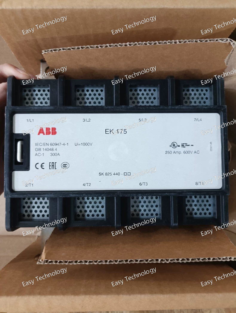
Technical Data Based on ABB's terminal block catalog, the standardized parameters for this model are as follows: Parameter Value / Description Manufacturer Part Number EK175-40-11 Series / Type EK 175 Main Earthing Terminal Block Connection Technology Spring-clamp (CAGE CLAMP® S) Rated Voltage (Ui) 1000 V AC/DC Rated Current (Ith) 175 A (This is the thermal current rating for the entire terminal block with connected conductors.) Number of Connection Points 40 (20 connection positions on each side, internally bridged to form a common busbar). Conductor Cross-Section (Solid/Flexible) 16 mm² - 50 mm² (For flexible wires, always use ferrules). Conductor Cross-Section (Fine-stranded with Ferrule) 16 mm² - 35 mm² Connection Capacity (per side) Accepts up to 2 x 35 mm² or 1 x 50 mm² conductors per connection point. Test Point Yes, integrated. Material (Housing) Transparent Polyamide (PA), Halogen-free, Flame-retardant (UL 94 V0). Material (Current Bar) Copper, Tin-plated. Clamp Material Stainless Steel. Mounting DIN-rail mounted (NS 35/7.5, NS 35/15, or G32 according to EN 60715). Width Approximately 264 mm (covers 15 modules on a DIN rail). Protection Rating (Housing) IP20 Operating Temperature Range -60 °C to +100 °C Approvals / Standards UL 1059, CSA C22.2, EN/IEC 60947-7-1, GL, CCC, etc. Recommended Torque (if applicable) Not required for spring clamps. The opening lever/actuator is designed for a standard screwdriver.
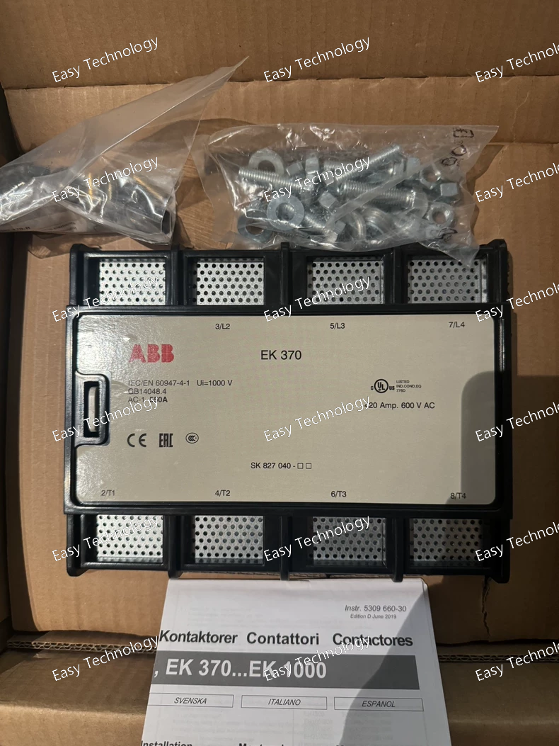
Technical Data Parameter Value / Description Manufacturer Part Number SK827040 Product Type Keypad / Operator Interface Panel for OmniCore Controller Compatible Controller Series ABB OmniCore (e.g., C30, C50, C90 models) Primary Interface Robot programming, jogging, monitoring, and system configuration. Display High-brightness color TFT touchscreen (Size typically 7" to 10" diagonal, exact size to be verified). Input Devices • Physical Joystick: For multi-axis manual robot guidance. • Dedicated Keys: For common functions like start, stop, speed override, coordinate system selection. • Alphanumeric Keypad: For data entry. • Function Softkeys: Associated with on-screen prompts. Safety Devices • Large Emergency Stop button (Dual-channel, meets safety standards). • 3-Position Enabling Device (Deadman switch) integrated into the side grip. • Mode Selector Switch (Typically for Auto, Manual, and Manual Reduced Speed modes). Connection High-speed, shielded cable with a ruggedized connector that plugs directly into the OmniCore controller's CPU unit. The cable is often several meters long and may be permanently attached or detachable. Protection Rating Typically IP54 or similar, providing protection against dust and water splashes for use in industrial environments. Mounting Mounts on a flexible, counter-balanced arm (usually ordered separately, e.g., SK830099) attached to the controller cabinet or robot cell frame. Software Runs the ABB RobotWare operating system and user interface. Weight Approximately 2-4 kg (depending on the specific model and cable).
Technical Data Parameter Value / Description Manufacturer Part Number 1SFL637025R7011 Product Line ABB OVR Quick Safe Type / Class Type 2 + 3 Combined Surge Arrester (Tested according to IEC/EN 61643-11) Application Plug-in SPD for point-of-use equipment protection. Rated Voltage (Un) 230V AC (Single-phase) Maximum Continuous Operating Voltage (Uc) 250 V AC Protection Level (Up) < 900 V (Very low clamping voltage for sensitive electronics). Nominal Discharge Current (In) 8/20 µs 5 kA (Type 2 component characteristic). Combination Wave (Uoc) 1.2/50 µs & 8/20 µs 2 kV (Open circuit voltage) / 1 kA (Short circuit current) – representing Type 3 test parameters. Maximum Discharge Current (Imax) 8/20 µs 10 kA Status Indicator LED (Green = Functional, Red = End-of-Life/Fault). Socket Outlet Standard Schuko socket (CEE 7/4), 2P+E, with child safety shutters. Plug Standard Schuko plug (CEE 7/4), 2P+E. Cable Length Integrated power cord, typically 1.5 meters (confirm with specific datasheet). Maximum Load Current 16 A (The maximum continuous current for the connected equipment). Standards & Certifications IEC/EN 61643-11, CE marked. Complies with socket safety standards.
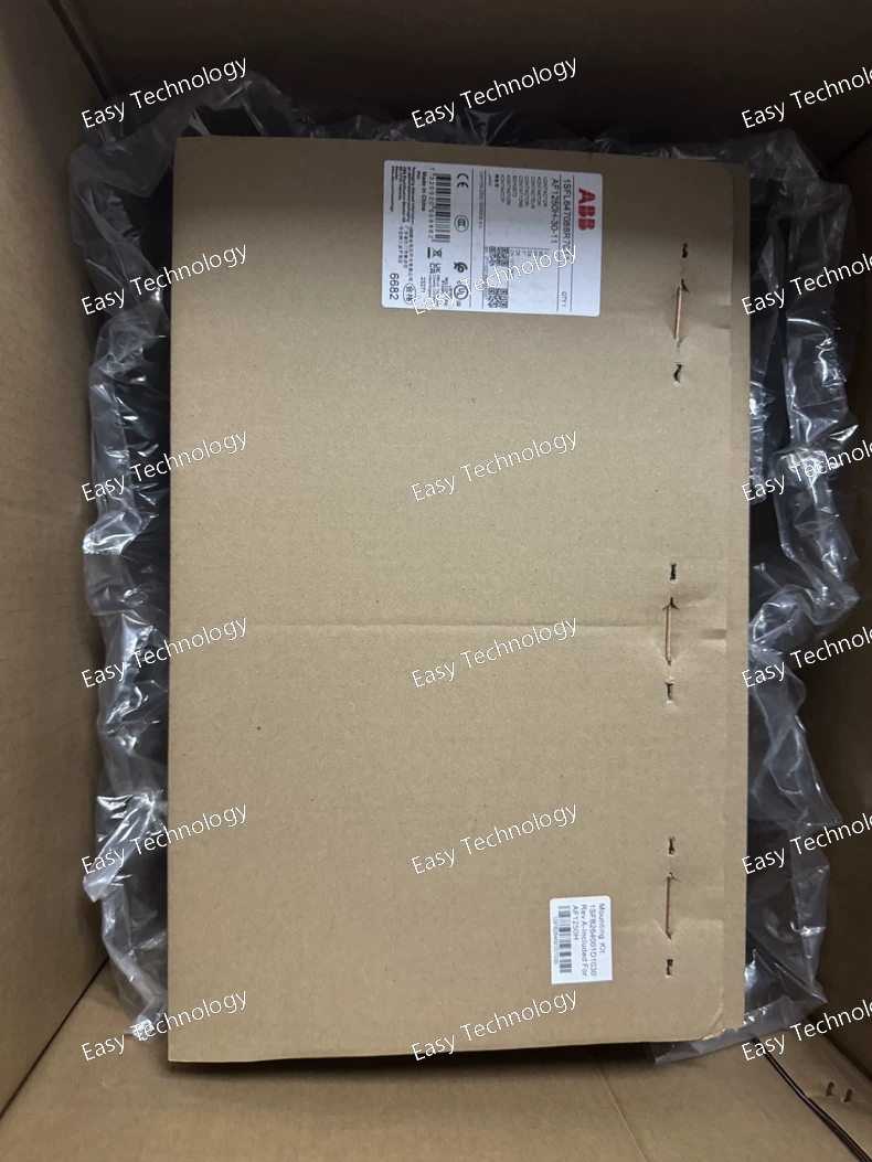
Technical Data Parameter Value / Description Manufacturer Part Number 1SFL647001R7011 Product Line ABB OVR Surge Protective Device Type / Class Type 2 Surge Arrester (Tested according to IEC/EN 61643-11) Rated Voltage (Un) 230/400V (for 50/60Hz AC systems) Maximum Continuous Operating Voltage (Uc) 320 V AC (between Line and Neutral). This is the voltage it can withstand continuously. Protection Level (Up) @ In ≤ 1.5 kV (measured at the rated discharge current In). This is the key parameter defining its clamping performance. Nominal Discharge Current (In) 8/20 µs 20 kA (per pole). Standard test current representing its duty cycle. Maximum Discharge Current (Imax) 8/20 µs 40 kA (per pole). The maximum single surge current it can handle once. Response Time < 25 ns Backup Fuse Recommendation Typically 63A gL/gG or as per local regulations. Must be verified in the installation manual. Number of Poles / Connection 1P (Single Pole, for protection of one phase line to neutral/earth). Multiple units are used for multi-phase systems. Technology Varistor-based (Metal Oxide Varistor - MOV). Status Indicator Visual window (Green = OK, Red = Fault/End-of-Life). Thermal Protection Integrated thermal disconnector. Mounting DIN-rail mounted (35 mm standard rail). Width 1 module (18 mm on a standard DIN rail). Standards & Certifications IEC/EN 61643-11, CE marked.
Technical Data Parameter Value / Description Manufacturer Part Number 1SF698108R7000 Product Type Plug-in Power Supply and Signaling Unit Compatible System ABB System Pro M compact®, System Pro E power® Primary Function Provides 24V DC auxiliary control voltage and status signaling for internal panel components. Input Voltage (AC) Typically designed for a standard single-phase AC supply, common range is 100-240V AC, 50/60Hz. (Must be verified with the enclosure's overall supply). Output Voltage (DC) 24V DC Output Current / Power Typically a low to moderate power output (e.g., in the range of 0.5A to 2A / 12W to 48W). Exact rating is critical and needs confirmation. Protection Overload and short-circuit protection on the DC output. Status Indication LED indicators: For signaling the presence of input power and the health/status of the DC output. Connection Plug-in connection to the back-mounting plate or busbar system within the ABB enclosure. Output terminals for connecting the 24V DC load circuits. Housing / Color Typically housed in a white or light-colored plastic module, matching the aesthetics of the System Pro M compact line. Mounting Snap-on mounting onto the DIN-rail inside the distribution board. Standards & Certifications Complies with relevant low-voltage directive and EMC standards.
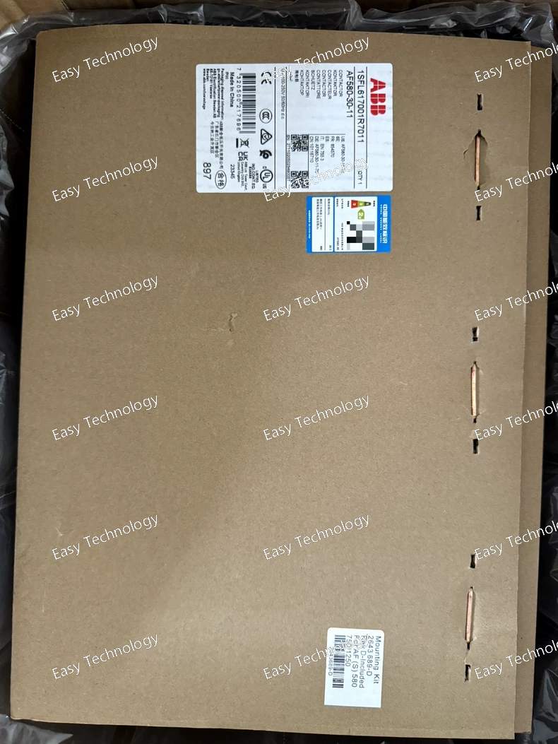
Technical Data Parameter Value / Description Manufacturer Part Number 1SFL617001R7011 Product Line ABB OVR Surge Protective Device Type / Class Type 1 + 2 Combined Surge Arrester (Tested according to IEC/EN 61643-11) Rated Voltage (Un) 230/400V (for 50/60Hz three-phase networks with neutral) Maximum Continuous Operating Voltage (Uc) 320 V AC (Line-Neutral) Protection Level (Up) @ In ≤ 1.8 kV (at rated discharge current In). This is the voltage that appears across the protected terminals, defining the clamping performance. Nominal Discharge Current (In) 8/20 µs 20 kA (per pole). The current waveform through which the device is tested for standard duty. Impulse Current (Iimp) 10/350 µs (Type 1) 12.5 kA (per pole). This is the critical parameter for withstanding partial direct lightning currents. Maximum Discharge Current (Imax) 8/20 µs 40 kA (per pole). The maximum single surge current the device can handle once. Response Time < 25 ns Backup Fuse Recommendation Typically 125A gL/gG (Must be verified with local regulations and the specific installation manual). Number of Poles / Connection 3P + N (Three Phase conductors + Neutral). Technology Varistor-based (Metal Oxide Varistor - MOV). Status Indicator Visual window (Green = OK, Red = Fault/End-of-Life). Thermal Protection Integrated thermal disconnector. Mounting DIN-rail mounted (35 mm standard rail). Width 4 modules (72 mm on a standard DIN rail). Standards & Certifications IEC/EN 61643-11, CE marked.
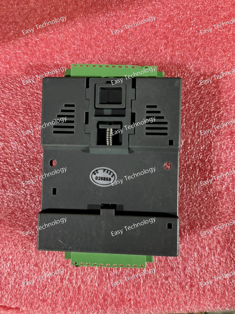
Technical Data Parameter Value / Description Manufacturer Part Number 2RJA024630A0001 Product Type I/O Extension Module / Control Interface Board Compatible Series ABB ACS880 Industrial Drives Primary Function Extends the standard I/O capability of the drive. Typical Interfaces Digital Inputs (DI): Several configurable, galvanically isolated inputs (e.g., 24 V DC sourcing). Digital Outputs (DO): Configurable relay or transistor outputs. Analog Inputs (AI): Configurable voltage or current inputs (e.g., 0/4-20 mA, 0-10 V). Analog Outputs (AO): Configurable outputs for signaling (e.g., 0/4-20 mA). Communication Interfaces with the drive's main control unit via an internal bus or direct connection (e.g., using ribbon cables or headers). Configuration Parameters are set via the drive's standard control panel or commissioning tool (e.g., ABB Drive Composer). Supply Voltage Typically powered internally from the drive's control voltage (e.g., 24 V DC). Isolation Galvanic isolation between field side and drive control electronics for noise immunity and safety. Mounting Installs into a dedicated slot on the drive's control unit or an adjacent module rack. Status Indication LEDs for power and channel status.
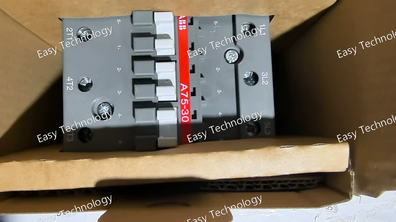
Parameter Value Rated Operational Voltage (Ue) 400 V AC (AC‑3 duty) Rated Operational Current (Ie) AC‑3 75 A at 400 V Rated Operational Current (Ie) AC‑1 125 A at 400 V Rated Control Supply Voltage (Uc) 110 V AC, 50 Hz / 110–120 V AC, 60 Hz Number of Main Poles 3 (NO) Auxiliary Contacts 1 NO + 1 NC Rated Insulation Voltage (Ui) 690 V AC Rated Impulse Withstand Voltage (Uimp) 6 kV Short-Circuit Making Capacity 6 kA (depends on fuse protection) Coil Type AC only, electromagnetic Terminal Type Screw terminals for main and auxiliary circuits Mechanical & Environmental: Parameter Value Mechanical Durability ~1,000,000 operations (typical for A75 series) Mounting Type DIN rail or screw mounting (block type) Ambient Operating Temperature −25 °C to +55 °C Storage Temperature −60 °C to +80 °C Protection Class IP20 (terminals), IP00 (main contacts) Connection Capacity Cu/Al wires as per terminal ratings Weight ~1.2 kg Applications: Control of three-phase motors (star/delta, direct-on-line) General AC power switching Lighting, heating, and capacitor bank control Suitable for AC‑3 duty, frequent switching operations
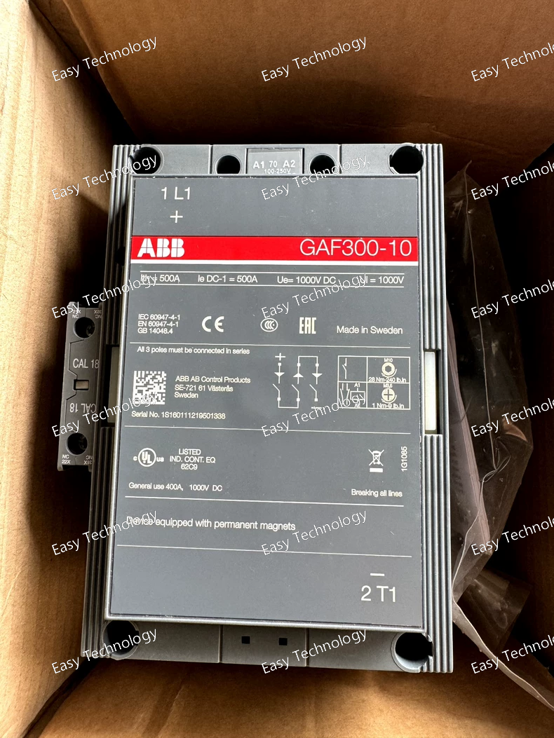
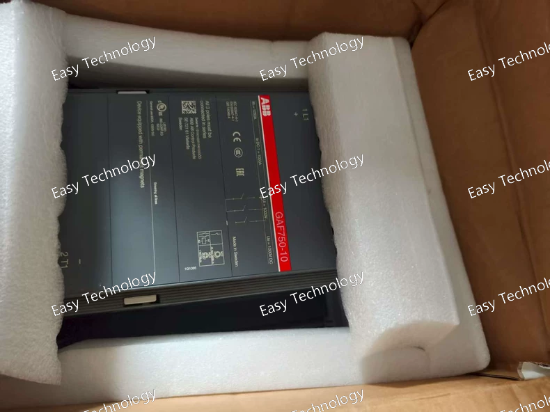
Specifications Electrical Ratings Rated Control Supply Voltage (Uc): 100–250 V AC/DC Rated Operational Voltage (Main Circuit): up to 1000 V DC Rated Operational Current DC‑1 (Ie): • 500 A at 1000 V, ambient 40 °C • 400 A at 1000 V, ambient 55 °C • 325 A at 1000 V, ambient 70 °C Conventional Free‑air Thermal Current (Ith): 500 A Maximum Breaking Capacity: ~3000 A at 440 V, ~2500 A at 690 V Rated Insulation Voltage (Ui): 1000 V Impulse Withstand Voltage (Uimp): 8 kV Contacts Main Contacts: 1 Normally Open (NO) per pole Auxiliary Contacts: 1 NO + 1 NC Coil / Control Control voltage range: 100–250 V AC/DC Coil consumption: holding and pull‑in vary by AC/DC Mechanical & Mounting Mechanical Durability: ~5 million operations Max Mechanical Switching Frequency: ~300 cycles/hour Connecting Capacity (Main): • Bars up to 32 mm² • Rigid Cu up to 240 mm² • Rigid Al up to 120 mm² Protection & Environment Degree of Protection: Coil terminals IP20; main terminals IP00 Operating Ambient Temp: −40 °C to +70 °C Storage Temp: −40 °C to +70 °C Altitude: up to ~3000 m RoHS Compliant: Yes Dimensions & Weight Width: ~140 mm Depth / Length: ~180.5 mm Height: ~227 mm Weight: ~5.5–5.8 kg Summary Type: 3‑pole DC contactor Main Use: Switching DC circuits (up to 1000 V) in DC‑1 duty Control Voltage: 100–250 V AC/DC Rated DC Current: Up to ~500 A depending on temperature Auxiliary Contacts: 1 NO + 1 NC Mechanical Life: ~5 million operations
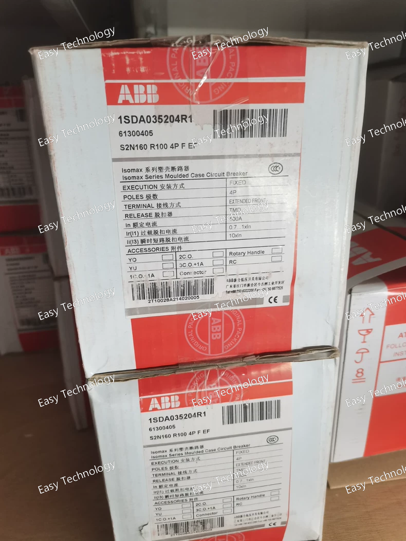
Specifications General Product Name: Molded‑Case Circuit Breaker (MCCB) Model: S2N160‑100A 4P EFE Series: ABB SACE Isomax S2N Number of Poles: 4 poles (4P) Terminal Type: Extended front terminals (EFE) for easier front cabling Electrical Ratings Rated Operational Current (In): 100 A (fixed thermal setting) Frame Rating: 160 A frame capacity (device frame size able to house adjustable protections around this rating) ABB图书馆 Rated Operational Voltage (Ue): Up to 690 V AC Rated Insulation Voltage (Ui): Typically 800–1000 V (standard for SACE breakers) Rated Impulse Withstand Voltage (Uimp): ~8 kV Rated Frequency: 50/60 Hz Short‑Circuit Breaking Capacity: Depends on specific trip unit and variants; standard S2N design supports high breaking capacities suitable for industrial distribution networks Thermal/Magnetic Trip: Thermomagnetic protection integrated for combined overload and short‑circuit response Standards: Designed according to IEC/EN 60947‑2 for low‑voltage circuit breakers Protection & Performance Overload Protection: Yes (thermal element) Short‑Circuit Protection: Yes (magnetic trip) Adjustability: Fixed trip settings for 100 A (some variants allow adjustable extensions within the 160 A frame) ABB图书馆 Neutral Pole: Full 4‑pole protection ensures neutral is also disconnected under fault conditions Mechanical Mounting: Panel / switchboard installation Connection: Screw or bolt front terminals (extended front) for cable sizes per frame rating Mechanical Endurance: High cycle life designed for industrial switching and protection applications Operating Temperature: Standard industrial ambient range Applications Overcurrent protection in three‑phase power distribution systems Protection of feeders, motor circuits, and branch circuits Use in switchgear and control panels Suitable for commercial and industrial electrical installations Typical Use Cases Main or sub‑distribution circuit protection Protection of machine feeders and motor circuits Integration in power panels where neutral disconnection is required Protection point near large loads such as HVAC, pumps, and industrial equipment
 TEL: Grace +86 13600179521
  Mail: info@hongkongeasy.com jilineasyyi@outlook.com
 Q Q:615739355
 ADDRESS:Unit 12, 20th Floor, Good View Commercial Centre, 2-16 Garden Street, Mong Kok, Hong Kong
 whats app


