Installation Process of DVC6215+6025 Valve Positioner for Iranian Client by Easy Technology
This document details the complete installation process of the DVC6215+6025 valve positioner carried out by Easy Technology's technical team for the Iranian client. The installation strictly adheres to the product manual of Fisher DVC6215 and DVC6025 valve positioners, as well as the client's on-site safety and technical specifications, ensuring the positioner operates stably and meets the industrial control requirements.
1. Pre-Installation Preparation
1.1 Equipment and Tool Checking
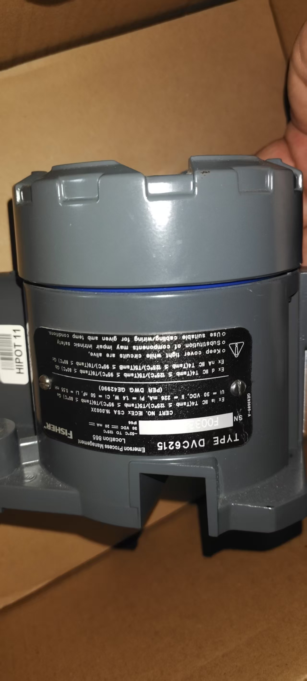
The technical team first verified the integrity and conformity of all equipment and tools at the client's site. The checked items included: DVC6215 main valve positioner, DVC6025 auxiliary positioner, mounting brackets, connecting rods, bolts and nuts (matching the valve model), signal cables (shielded twisted-pair cables), power cables, calibration tools (such as HART communicators, pressure gauges with an accuracy of 0.1%), wrenches, screwdrivers, wire strippers, and insulation tape. All equipment was confirmed to have no transportation damage, and the model numbers matched the order requirements. The calibration tools were calibrated within the valid period to ensure measurement accuracy.
1.2 Site Safety and Environment Confirmation
In collaboration with the client's on-site safety supervisor, the team conducted a safety assessment of the installation area. They confirmed that the site had good ventilation, no flammable, explosive, or corrosive gases, and the ambient temperature was between -20°C and 60°C, which met the operating environment requirements of the DVC6215+6025. Safety measures such as warning signs, isolation barriers, and fire extinguishers were set up around the installation area. All operators wore personal protective equipment (safety helmets, anti-static work clothes, and safety shoes) and passed the on-site safety training provided by the client.
1.3 Valve and Pipeline Status Confirmation
The team checked the target valve (model confirmed with the client) to ensure it was in the "closed" state and that the pipeline connected to the valve was depressurized and isolated. The valve stem was manually operated to confirm its flexibility without jamming, and the valve body had no obvious wear or leakage. The mounting position on the valve was cleaned to remove dust, rust, and oil stains, ensuring a firm installation of the positioner.
2. Installation of Main Components
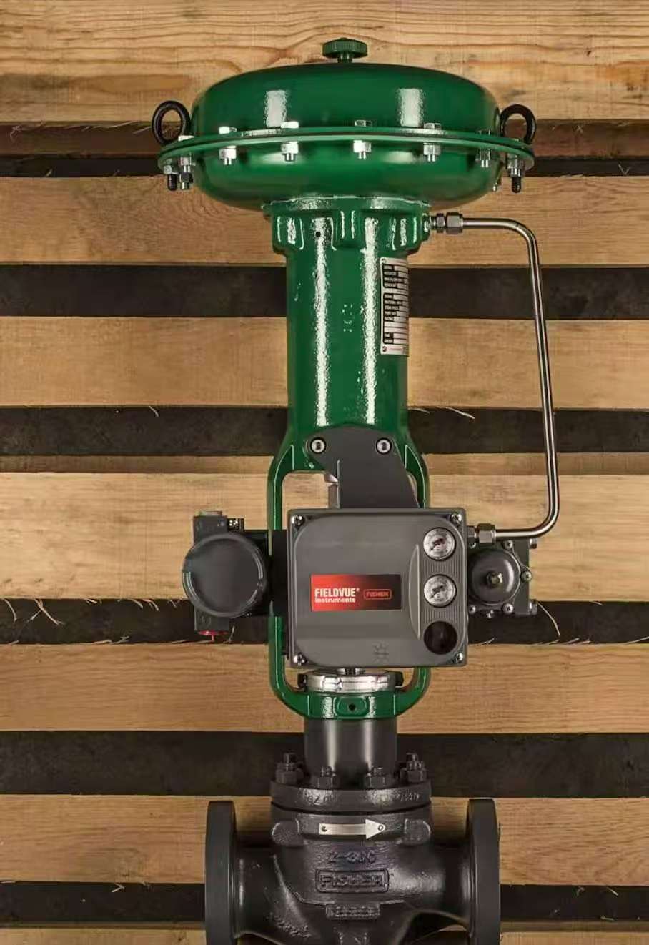
2.1 Mounting of DVC6215 Main Positioner
The mounting bracket was fixed to the designated position on the valve using bolts and nuts. The bracket was adjusted to ensure it was horizontal and vertical, with no tilting. The DVC6215 main positioner was then mounted on the bracket and tightened with fixing bolts to prevent looseness caused by vibration during operation. During installation, attention was paid to aligning the positioner's feedback lever with the valve stem to ensure smooth transmission of the valve's opening signal.
2.2 Mounting of DVC6025 Auxiliary Positioner
Based on the site layout and signal transmission requirements, the DVC6025 auxiliary positioner was mounted near the DVC6215 main positioner (within 1 meter). It was fixed using a separate bracket or directly mounted on a stable platform nearby. The distance between the auxiliary and main positioners was controlled to reduce signal loss and ensure stable communication. The auxiliary positioner's wiring port was oriented downward to prevent rainwater or dust from entering, which is crucial for adapting to the on-site environment.
2.3 Connection of Mechanical Linkage Mechanism
The connecting rod was used to connect the feedback lever of the DVC6215 main positioner to the valve stem. The length of the connecting rod was adjusted to ensure that when the valve was fully open or fully closed, the feedback lever of the positioner moved within the full stroke range (0-100%) without exceeding the limit. The joint of the connecting rod was locked with a lock nut to prevent loosening. After connection, the valve was manually operated to check the flexibility of the linkage mechanism, ensuring no jamming or dead points.
3. Wiring and Circuit Connection
3.1 Wiring of Power Supply
Before wiring, the power supply was confirmed to be cut off, and a multimeter was used to verify that there was no residual voltage. The power cable was stripped (exposing 3-5mm of the conductor) and connected to the power terminal of the DVC6215 main positioner (complying with the "positive to positive, negative to negative" principle; the power supply specification was 24V DC, consistent with the positioner's rated voltage). The wiring terminal was tightened to prevent poor contact. The power cable was fixed with cable ties to avoid pulling or damaging the wiring during operation.
3.2 Signal Wiring Between Main and Auxiliary Positioners
Shielded twisted-pair cables were used to connect the signal output terminal of the DVC6215 main positioner to the signal input terminal of the DVC6025 auxiliary positioner. The shielding layer of the cable was grounded at a single point (connected to the client's on-site grounding system) to reduce electromagnetic interference, which is particularly important for industrial sites with complex electromagnetic environments. The wiring was labeled clearly (e.g., "DVC6215-SIG-OUT to DVC6025-SIG-IN") for subsequent maintenance.
3.3 Connection to Control System
The signal output terminal of the DVC6025 auxiliary positioner was connected to the client's DCS (Distributed Control System) using shielded twisted-pair cables. The connection point was confirmed with the client's instrument engineer to ensure the signal type (4-20mA analog signal) matched the control system's input requirements. After wiring, the cable entry of the positioner was sealed with waterproof and dustproof tape to enhance environmental protection.
4. Calibration and Parameter Setting
4.1 Power-On Self-Check
After completing the wiring, the power supply was turned on, and the DVC6215+6025 positioner entered the self-check mode. The technical team observed the indicator lights of the main and auxiliary positioners: the green light was on steadily, indicating normal power supply; there was no red light flashing, indicating no hardware failure. The self-check process lasted for 30 seconds, and the positioner entered the standby mode after the self-check was passed.
4.2 Zero and Span Calibration
A HART communicator was connected to the communication port of the DVC6215 main positioner to perform zero and span calibration. First, the valve was manually adjusted to the fully closed position, and the "Zero Calibration" function on the HART communicator was activated. The positioner automatically recorded the zero position signal. Then, the valve was adjusted to the fully open position, and the "Span Calibration" function was activated to record the full-stroke signal. During calibration, a pressure gauge was used to monitor the output pressure of the positioner, ensuring it matched the valve's rated pressure (confirmed with the client). After calibration, the valve was operated repeatedly 3 times to verify that the zero and span values were stable without deviation.
4.3 Parameter Configuration
According to the client's process requirements, key parameters were configured through the HART communicator, including: valve action mode (fail-open/fail-close, set to "fail-close" as required by the client), response speed (adjusted to 1.2s based on the pipeline pressure characteristics), signal filtering level (set to level 3 to adapt to on-site vibration), and auxiliary positioner communication address (set to 02 to avoid address conflict with other instruments). Each parameter was confirmed with the client's technical representative before setting, and the setting results were saved in the positioner's memory.
5. Functional Test and On-Site Debugging
5.1 Manual Control Test
The HART communicator was used to send manual control signals (4mA, 12mA, 20mA) to the DVC6215 main positioner. The team observed the valve's opening degree and the positioner's feedback signal: when the input signal was 4mA, the valve was fully closed, and the feedback signal was 0%; when the input signal was 12mA, the valve was half-open, and the feedback signal was 50%; when the input signal was 20mA, the valve was fully open, and the feedback signal was 100%. The test was repeated 5 times, and the valve action was accurate and smooth, with no overshoot or lag.
5.2 Automatic Control Test
The client's DCS system was operated to send automatic control signals to the positioner. The team monitored the real-time data of the DCS system and the on-site valve status: when the DCS sent a "50% opening" command, the valve quickly adjusted to the half-open position, and the feedback signal was transmitted back to the DCS within 1s, realizing closed-loop control. During the test, the pipeline was slowly pressurized to the working pressure (6MPa, as required by the client), and the valve had no leakage, and the positioner's output pressure remained stable.
5.3 Fault Simulation Test
To verify the reliability of the positioner, fault simulation tests were conducted: the power supply was temporarily cut off, and the DVC6215+6025 positioner drove the valve to the pre-set fail-close position within 2s, meeting the client's safety requirements. The signal cable was temporarily disconnected, and the positioner sent a fault alarm signal to the DCS, and the alarm information was accurate and timely. After the fault was eliminated, the positioner resumed normal operation without manual reset.
6. Acceptance and Handover
6.1 Installation and Test Record Sorting
The technical team sorted out all installation and test data, including: equipment inspection records, calibration reports, parameter setting sheets, functional test records, and fault simulation test reports. All records were filled in truthfully and signed by the on-site operators. The records were translated into both English and Persian to facilitate the client's review and archiving.
6.2 On-Site Acceptance by the Client
The client's technical team and safety supervisor conducted on-site acceptance. They rechecked the installation firmness of the positioner, the correctness of wiring, and the accuracy of parameter settings. They also randomly sent control signals through the DCS to verify the valve's action accuracy and feedback timeliness. After the acceptance, the client confirmed that the DVC6215+6025 valve positioner met all technical requirements, and signed the "Installation and Acceptance Certificate".
6.3 Training and Handover
The Easy Technology team provided on-site training for the client's operation and maintenance personnel, covering: basic structure and working principle of the positioner, daily inspection items (such as indicator light status, linkage mechanism flexibility), simple fault diagnosis and handling methods (such as zero deviation adjustment, signal interference troubleshooting), and use of the HART communicator. The training materials (including product manuals and operation guides) were handed over to the client. The team also left contact information to provide technical support for subsequent problems.
7. Post-Installation Follow-Up
Three days after the installation, the Easy Technology team conducted a remote follow-up with the client to confirm that the positioner operated stably without abnormal phenomena. One week later, a follow-up visit was conducted on site to check the wear of the linkage mechanism and the tightness of the wiring terminals, and to answer the client's questions about daily maintenance. The follow-up records were archived to form a complete service closed loop.
This installation process strictly follows international industrial standards and the client's personalized requirements. The whole process emphasizes safety, accuracy, and reliability, ensuring that the DVC6215+6025 valve positioner can effectively improve the control accuracy of the client's industrial process and reduce maintenance costs.


 TEL: Grace +86 13600179521
  Mail: info@hongkongeasy.com jilineasyyi@outlook.com
 Q Q:615739355
 ADDRESS:Unit 12, 20th Floor, Good View Commercial Centre, 2-16 Garden Street, Mong Kok, Hong Kong
 whats app


